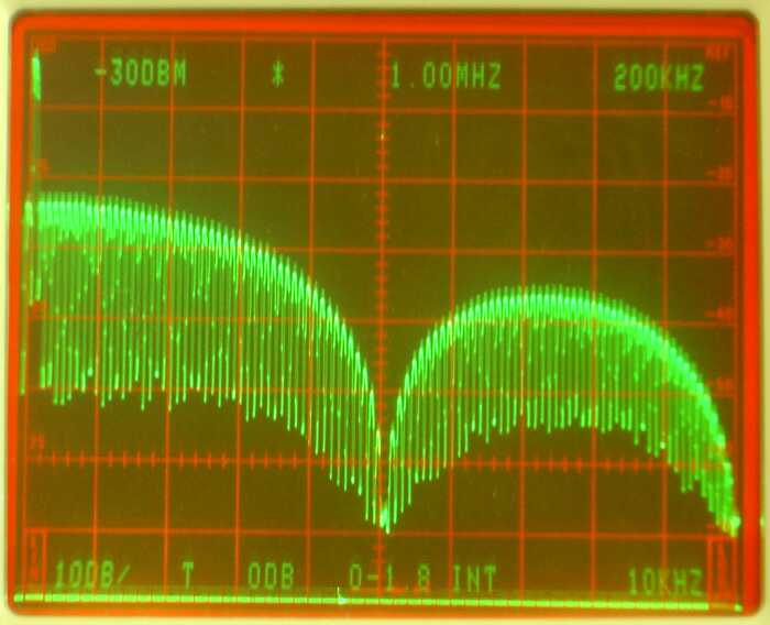
Fig 1. The spectrum of a 1 microsecond pulse having a repeat rate of 20 kHz.
Calibration of filter responses in LinradLinrad needs to know the frequency response of the hardware it is connected to in order to produce optimum processing.There are two ways of obtaining the frequency response of a filter. The obvious one is to send a sine-wave through the filter and measure the attenuation at different frequencies. That way the amplitude vs frequency curve can easily be obtained. The phase vs frequency curve is obtained by measurement of the phase shift from input to output at different frequencies. When the "filter" is a radio receiver run in linear mode (CW or SSB without AGC) the amplitude measurement by stepping a signal generator is straightforward and often used, but the phase measurement is difficult because one has to extract all local oscillators from the receiver and mix the test signal with them to get a signal at the loudspeaker output frequency to use as the reference phase. The reference signal must have a known phase shift over the frequency range of interest, typically it is constant and can be neglected since receivers generally have a narrow bandwidth in linear mode. The measurement in the frequency domain with a signal generator allows a very large dynamic range because the attenuator on the signal generator can be adjusted for the loudspeaker output to not saturate, but the accuracy of each data point is limited. Reading amplitude levels to better than a few percent is difficult and when using an attenuator the uncertainty is typically 0.5 dB (6% amplitude.) The other, perhaps less obvious way of measuring a filter is to do it in the time domain by sending a wideband pulse through the filter and then analyze the pulse response. This is done by use of a pulse generator. Pulses have wide spectra that can be assumed to be totally flat within a narrow frequency range. The spectrum of an infinitely short pulse is totally flat and infinitely wide, but it contains an infinitely small amount of energy because the amplitude must be within the range for which the test object has a linear (non-saturated) response. A limited amplitude during an infinitely short time means an infinitely small power. A low frequency square wave with 50% duty has a spectrum containing odd overtones that falls off by 6 dB each time the frequency is doubled up to a limit that is set by the rise and fall times. This link A simple squarewave generator. shows a generator that is useful up to 144 MHz on receivers like the IQ+ that have a good bandpass filter on the input. Receivers like rtl-sdr dongles that do not have an input filter need a filter between a pulse generator and the antenna input. A rectangular pulse, a square wave with a duty cycle far from 50% has more energy in each pulse as compared to a square wave in the mid frequency range but the spectrum has an oscillatory behaviour at high frequencies. Figure 1 shows the spectrum of a 1 microsecond pulse with a repeat frequency of 20 kHz. There is a minimum at 1 MHz where the pulse duration matches one period of the frequency. This overtone spectrum contains odd and even overtones at nearly the same amplitude. When the duty is near 0% odd and even overtones have the same amplitude. Figure 2 shows the spectrum of a 10 kHz square wave. This spectrum contains odd harmonics only so the separation between the (strong) overtones is the same as in figure 1 reflecting the fact that the pulse repetition frequency as seen through a band pass filter at RF frequencies is the same, 20 kHz, in both cases. When the signal is routed through a filter that is wide enough for the pulses to be well separated in the time domain the spectrum of each individual pulse is the same in both cases as long as the bandwidth is small enough for all overtones within the passband to have equal amplitudes in figures 1 or 2. | |

Fig 1. The spectrum of a 1 microsecond pulse having a repeat rate of 20 kHz. | |
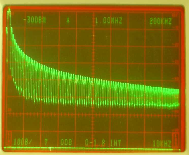
Fig 2. The spectrum of a 10 kHz square wave. | |
|
Figure 1 and 2 are obtained with a function generator (Escort EGC-2230)
set for an amplitude of 27 mV into the spectrum analyzer so the
power levels in the two figures can be compared directly.
What waveform to use depends on the frequency and bandwidth of the
filter one wants to investigate.
When a squarewave is used, the bandwidth must be much smaller than
the frequency of operation since the pulse amplitude always falls like 1/F
which means that F has to be nearly the same at both ends of the
passband.
The 1 us pulse has a flat spectrum up to 100 kHz and can be used
for a bandwidth of about 5 kHz at 500 kHz.
A pulse length of 20 ns gives a flat spectrum up to about 5 MHz with a fall-off that is slow enough to make it suitable for calibration at a bandwidth of up to 1 MHz at frequencies up to 25 MHz. Shorter pulses can be used at higher frequencies, but the energy of each pulse becomes smaller. A pulse length of 5 ns is suitable at 144 MHz, but it may be difficult to get a good S/N for such a pulse because being 5 times shorter and spread out over a 5 times wider frequency range the power density (dBm/Hz) is 25 times smaller than for the 20 ns pulse. For calibration at 144 MHz one should use an LC bandpass filter with a flat bandwidth of about 5 times more than the desired bandwidth. This way the pulse is smeared out in time to a damped oscillation with a smaller amplitude allowing a higher level of the original 5 ns pulse. For more details look here A pulse generator for receiver calibration At the optimum frequency for a short pulse, about 500 kHz in figure 1, the signal level of the pulses produced by a square wave is about 6 dB weaker. Both the rising and the falling edges add their energy into the pulse at this frequency. If the square wave has low noise this does not matter and Linrad can be calibrated by use of square waves as well as by use of short pulses. Requirements on a pulse generator for Linrad calibration.1. The spectrum of the pulses has to be flat over the frequency range of interest. Linrad provides no help - this is the operators responsibility.2. The pulse repetition frequency must be low enough for the pulses to be completely resolved in time. A filter converts a short pulse to a damped oscillation that oscillates for a time related to the Q of the filter which in turn is related to the skirt steepness. The first screen of the calibration sequence helps for this. 3. The pulse repetition frequency must be low enough for Linrad to evaluate the lowest frequency of interest. The pulse repetition frequency should not be higher than half the lowest frequency of interest. When a normal radio is used half the frequency of the -10 dB point could be suitable. Setting a high pitch is a good idea since this requirement then becomes fullfilled by the previous requirement while the overtones of the mains frequency come outside the passband. When direct conversion or digital hardware is used to provide I and Q, the lowest frequency of interest depends on how wide center notches one can interpolate across with good enough accuracy. Linrad provides no help - this is the operators responsibility - but generally a low repetition frequency is better as long as S/N does not become too low or the time to calibrate becomes too long. 4. The signal to noise ratio must be good enough. A square wave that uses a digital IC to switch between VCC and GND should have very low noise, but only if VCC is well decoupled and the GND voltage is properly referenced to the output ground. Spurs and the mains frequency and its overtones must have low levels compared to the pulse amplitude to allow correct calibration. The calibration procedure.It is advantageous to use the lowest possible frequency for calibration. When converters are used to bring the antenna signal to lower frequencies, For example when using a 144 to 28 MHz converter followed by a direct conversion receiver at 28 MHz it is better to inject the pulses at 28 MHz assuming that the converter has a flat frequency response over the frequency response of interest. Likewise it is better to calibrate a WSE converter chain at 10.7 MHz rather than at 144 MHz. Using the 2.5 MHz input is not a good idea since the frequency response of the 2.5 MHz filters inside the RX2500 will depend slightly of the input impedance seen by the RX2500 so it is better to allow it to see the actual output impedance of the RX10700 to which it will be connected in actual usage.To reach the calibration procedure, press X while Linrad is running in one of its receive modes. The screen showed in fig.3 will then appear. Choose C to get into the calibration menu which will look like figures 4 or 5 depending on whether a direct conversion hardware is used or not. | |

Fig 3. The menu after pressing 'X' in any receive mode. | |

Fig 4. The menu after pressing 'C' on the menu of figure 3 when a real-valued signal is produced by the hardware or if digital hardware that automatically has perfect balance between I and Q is in use. | |

Fig 5. The menu after pressing 'C' on the menu of figure 3 when direct conversion hardware is in use. | |
|
In IQ mode, the phase and amplitude balance between I and Q should be
have been done already, as described here:
Calibrate for phase and amplitude errors
between the I and Q signals in a direct conversion receiver.
To enter the filter calibration, press the key for Calibrate total amplitude and phase The links below give several examples of the calibration on different hardware with files containing the actual calibration pulses as wav files or as files in Linrads own format. These files will allow you to do the calibration without any hardware at all and to verify that you understand what to do and why. Two channels with real-valued signals shows calibration with a 50 Hz square wave on a two channel receiver with crystal filters. The focus is Calibrate total amplitude and phase. Check this link before you look at the ones below in case you are not already familiar with Linrad. One channel with direct conversion hardware shows calibration on 3.6 MHz with the WSE converters using square waves. The focus is Remove center discontinuity. Calibration with poor S/N. Here an antenna was connected to simulate leak-through of RF signals. The focus is Refine amplitude and phase correction Hardware linearity.It is normal for a wideband pulse to saturate the wideband amplifiers of the receiver front end. Not only ignition pulses, powerline noise and other truely wideband pulses may saturate a front end. Also radar systems near microwave bands may cause saturation.Saturation at a wide bandwidth is completely harmless as long as no narrowband signals come close to the saturation level and cause intermodulation. When a pulse saturates, its amplitude becomes lower and its shape becomes different. If the wideband pulse is still much shorter than the pulse response of the bandwidth defining filters even after the pulse amplitude is limited by wideband amplifier saturation, the calibration will still correct. One only has to worry about the recovery time. The wideband amplifiers have to recover very fast after saturation because if they do not, all strong narrowband signals will have a too low amplitude for a while after the pulse. A big capacitor together with a high DC impedance on the gate of a FET can cause a recovery time of milliseconds and that would cause severe keying clicks from all strong signals. Saturation in amplifiers that operate in a limited bandwidth will change the pulse response that Linrad records and thereby cause an incorrect frequency response. Once you have calibrated, verify the calibration by running Linrad on the calibration signal with averaging on the main spectrum and waterfall graph. The spectrum you see should be very flat with deviations of only a small fraction of a dB from the ideal response. This response should not change when you insert an attenuator. If it does, your hardware has linearity problems and you should calibrate at a lower pulse level in order to get a flat frequency response for the normal noise floor. Figures 6 to 9 show averages over several seconds for the WSE converters when calibrated with very strong pulses, only 1 dB below A/D converter saturation. The calibration signal is a 50 Hz square wave that produces 2.7 V across 50 ohms. The calibration is not quite correct for other signals because of the phenomenon illustrated in figure 2, but this small error is independent of the amplitude. The calibration square wave was fed into the RXHFA unit at 1.85 MHz with maximum gain, +10 dB. The output from the RXHFA is a pulse with an RMS amplitude of 1.9 volts across 50 ohms (+19 dBm) and a duration of about 1.5 microseconds. Figure 6 shows the pulses at the same signal level as where the calibration was performed. As expected, the spectrum is very flat. With a 3 dB attenuator, figure 7, the spectrum is not quite flat any more. But with 20 and with 40 dB attenuation the spectrum shape is identical as shown in figures 8 and 9. The conclusion is that +19 dBm is a bit too much power output from a RXHFA. Not very surprising because input IP3 is +19 dBm and the gain is 5 dB for an output IP3 of +24 dBm. The calibration pulse is actually 3 dB above the 1 dB compression point of the RXHFA and the reason the calibration error is so small is that the bandwidth of the RXHFA is big enough compared to the visible bandwidth of 93 kHz. | |
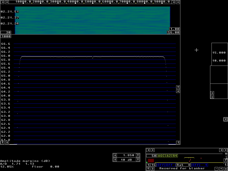
Fig 6. Very strong pulses averaged over a long time on a system calibrated with the same pulses. | |

Fig 7. The pulses of figure 6 with a 3dB attenuator. | |
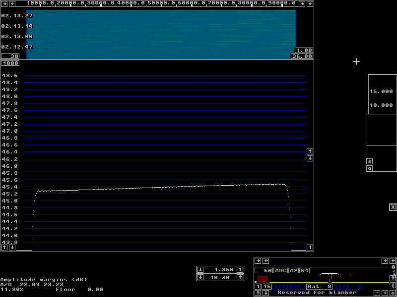
Fig 8. The pulses of figure 6 with a 20dB attenuator. | |
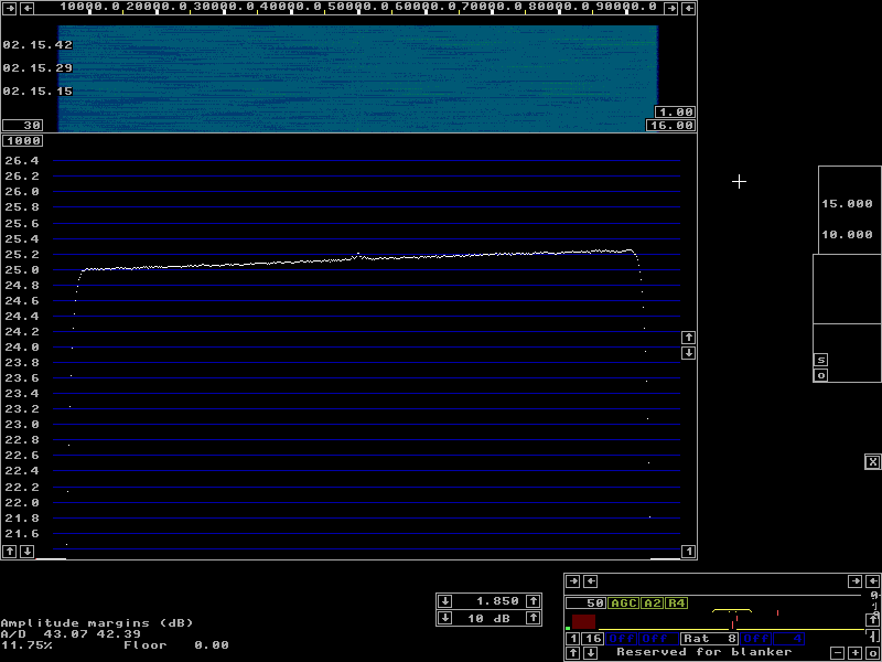
Fig 9. The pulses of figure 6 with a 40dB attenuator. | |
Impedance.The response of an LC filter depends on its source and load impedances. With WSE units on 1.8 MHz, a 300 ohm resistor across the RXHFA input will cause a change of the noise floor that is similar to the difference between figures 6 and 8. This is the change for pulses well within the linear range of the system.The WSE system is easiest to calibrate at the RX10700 input or through the RXHFA at 7 MHz or so. Calibrating at the RX2500 input is not recommended because that would require a pulse source that has an output impedance that is very similar to the particular RX10700 in use. |