Pulse generator for receiver calibration.The pulse generator described here is useful from 1MHz to 150MHz for calibrating digital receivers. The pulse repetition frequency is unstable enough to make sucessive pulses uncorrelated, the phase of one pulse is random compared to surrounding pulses at repetition rates of 100Hz and below.The pulse generator uses two 74AC04 which have VCC extremely well decoupled. VCC of the 6 parallelled invertors of the output IC is not only well decoupled, it is also connected to VCC through a low pass filter (an inductor) to isolate the output from weak pulses before the main pulse. The multivibrator produces a square wave between from 2Hz and 2MHz depending on the setting of the logarithmic 2.2 megohm potentiometer. The noise source is a zener diode followed by two transistors that amplify the noise.
|
Fig. 1. Schematic diagram of pulse generator for calibration purposes.
|
The 180pf and 100nH form a series resonator at about 50MHz.
Because of the diode the invertor after will just see the
the first half period that lasts 10ns. The peak amplitude is
nearly 5 volts and stays above the threshold of the next
invertor for about 5ns.
Only the negative going edge of the multivibrator produces
an output pulse.
The positive edge produces a very weak transient at the output
and because the phase is uncorrelated it will average out together
with the white noise of the receiver noise floor.
The output is 5V pulses that can be loaded by a 50 ohm load. The spectrum is reasonably flat with a typicall low pass characteristic. The amplitude has a wide maximum around 100MHz where the level is 2dB above the level at shortwave frequencies. At 150MHz the level has fallen to 5dB below the level at shortwave frequencies.
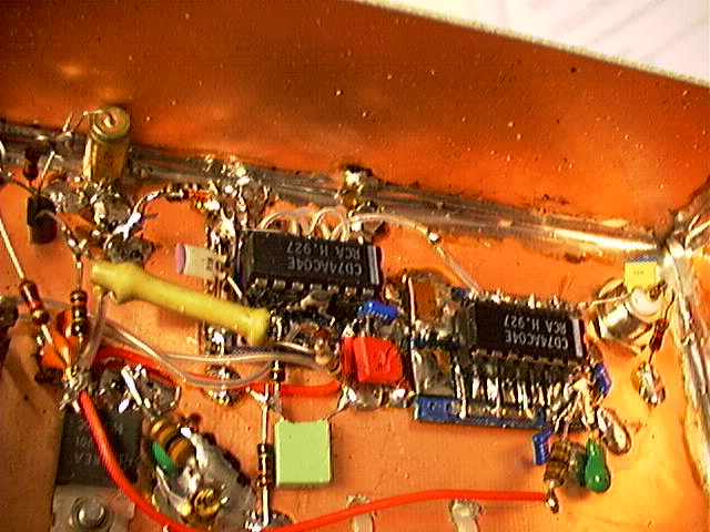
Practical design considerationsThis pulse generator is a 150MHz amplifier with very high gain (during the switching). To make it work properly it is very important to have extremely good decoupling of VCC and to have a very good ground reference.For this kind of equipment it is very convenient to cut small rectangles, typically 20 x 25 mm from one sided PC boards having a pattern on top of which one can solder a IC socket. Use a knife on a standard test board with parallel lines of copper on it. As long as there are no via holes and no wires on the other side any copper pattern will not matter but if one wants to put wires there it is wise to remove all copper. Pins can be connected on the back side using thin wire on which thin teflon tube is slided for isolation. Each small PCB is placed on top of the main ground plane, the copper laminated standard PCB material from which the box itself is done. The ground pin is connected with very low inductance to the ground plane and VCC is decoupled to it. See fig. 2. Poor decoupling may cause pulses that are multiple pulses causing a pulse amplitude that varies with frequency. A short pulse train will be strong at some frequency and very weak at some other. The second PCB gets VCC through an inductor to isolate it well from the transients on VCC of the first IC.
|
5V pulses need selective amplifiersThe 5V pulses of this amplifier produce 0.5W in a 50 ohm load - but only during 5 nanoseconds. If the pulse is fed directly into a wide band amplifier, the amplifier is saturated and the output pulse is not much amplified - it may even become severely attenuated. If the calibration pulses are used without selective rf filters they have to be fed to the mixer through an attenuator which brings the pulses down from 27dBm to whatever level the mixer can handle. A very good schottky mixer can handle +20dBm (2.2V RMS) and saturates at about 3V peak.When a 3V 5ns pulse is fed into the mixer of the dsp radio system, the amplitude at the A/D converter is not very high. Even at a large bandwidth of 90kHz only a very small fraction of the signal energy, 90/150000 is within the passband. That means that the amplitude seen by the computer only corresponds to 50 millivolt RMS at the receiver input. To get a good S/N for the calibration pulses a narrow filter followed by an amplifier should be inserted between the pulse generator and the receiver mixer. By picking out about 0.5MHz of the frequency range the single pulse is converted to a damped oscillation that lasts about 2 microseconds and has a peak amplitude of about 300 millivolts or about 0 dBm. Such a pulse can be amplified by about 20dB with a conventional front end amplifier. The calibration routines need a narrow band amplifier in order to work properly with the direct conversion hardware two frequency mixers in quadrature and anti alias filters used in the program development. There are two reasons. Firstly the pulse is not high enough above the noise floor. Secondly, the direct conversion receiver always needs an input filter because the mixer will mix not only with the local oscillator. It will also mix with all the overtones of the LO so if pulse energy at the overtone frequencies is allowed to reach the mixer the resulting curve form may be seriously in error causing incorrect calibration. A normal radio, such as the TS520 does not need any external selective amplifier. They are already present inside the transceiver.
| |