
Fig 1. Enable automatic spur cancellation like this.
A DSP challenge
Theory of operationLinrad has a number of digital PLL's (phase locked loops) that can be locked to phase stable signals that are present in the input spectrum.The general theory about PLL's is described by many others and there is no reason to go deeply into it here. Basically a digital LO (local oscillator) is set up with the same frequency as the offending spur. The LO is used in two mixers to produce I and Q (quadrature mixing) and Q is used to control the phase/frequency of the LO through an appropriate loop filter. The LO of the PLL has ideally the same phase as the spur. The spur amplitude is the I signal. In the presence of noise there will be errors in the LO phase and the I signal, but by selecting a narrow loop filter and filtering I through a similar filter the noise can be suppressed. Once the amplitude and phase of the spur is known a signal with the same amplitude and opposite phase can be generated and added to the wideband signal before it is further processed. This way the spur is cancelled without any effect on desired signals at the same frequency, provided that the desired signals have much larger bandwidth than the bandwidth of the loop filter. Selecting parameters for spur removal.As a first step, select 2 for automatic spur removal as shown in figure 1. | |

Fig 1. Enable automatic spur cancellation like this. | |
|
The spur removal will operate on the second FFT if it is enabled,
if not it will operate on the first FFT.
The bin bandwidth of the FFT must be larger than
the bandwidth of the spur one wants to remove.
Too much bandwidth will degrade S/N in the phase locking process
causing the spur removal to fail on weak spurs.
There are two parameters that affect the spur removal. The maximum number of spurs and the spur time constant. See figure 2. | |
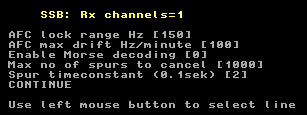
Fig 2. Here maximum 1000 spurs can be removed and the bandwidth of each notch is about 5 Hz (the time=0.2 seconds). | |
It should be obvious that aggressive settings for the spur removal,
large bin bandwidth and short time constant will produce wide
notches that will find and remove the carriers of stable
CW transmissions.
On the other hand, many real life spurs do not have the phase
stability required for notch bandwidths below a few Hz.
A practical example of the automatic spur removal.This file http://www.sm5bsz.com/linuxdsp/spur/file1/20mnoise1.raw (14 916 809 bytes) was recorded by Roger, W3SZ, on 20 meters. To use this file as input to Linrad in order to experiment with interference reduction, place the file in a directory /demo if you run under Linux or in a directory c:\demo if you run under Windows. Note that this file contains incorrect calibration data.Figure 3 shows the Linrad screen for the 20mnoise1.raw file without any blanker or spur removal routine. Like all .raw files saved by Linrad, this file has a header with various pieces of information. This particular file was recorded on a system that contained calibration data from another WSE system so calibration was incorrect. The 20mnoise1.raw file therefore contains calibration data that does not match the recording and as you can see in figure 3 the noise floor is far from flat. The blankers operate well despite this, but the noise floor is not very flat. In Linrad-02.41 and later there is a .raw to .wav file converter. With the 20mnoise1.raw file as input it produces the file 20mnoise1.wav(13258796 bytes) which is a standard 16 bit wav file that can be used with Winrad and other SDR software. The zipped file is available here: http://www.sm5bsz.com/linuxdsp/spur/file1/20mnoise1.zip (9546443 bytes) Figure 4 shows the Linrad screen processing the 20mnoise1.wav file without any interference fighting. and without any calibration files present in the Linrad directory. | |

Fig 3.No blanker, no spur removal. Input is 20mnoise1.raw with incorrect calibration. | |
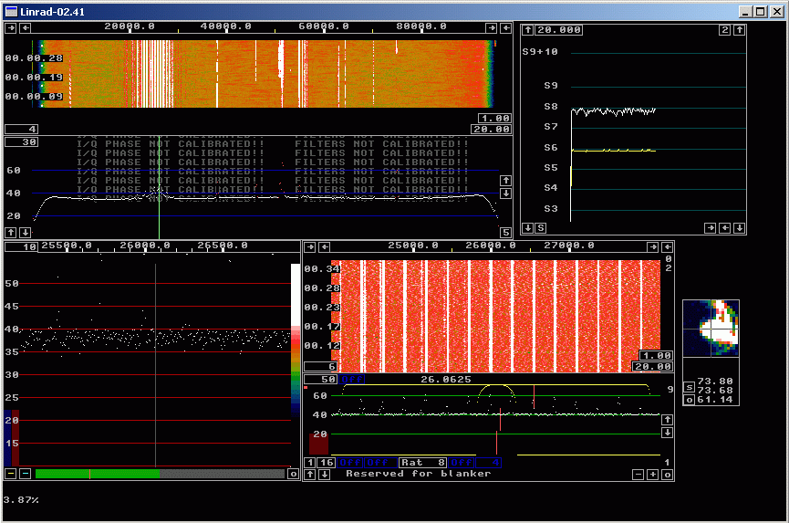
Fig 4.No blanker, no spur removal. Input is 20mnoise1.wav without calibration. | |
|
This file
http://www.sm5bsz.com/linuxdsp/spur/file1/20mcalpul.zip (3681343 bytes)
contains pulses recorded with the same WSE converters that were used
about two months earlier to record the 20mnoise1.raw file.
When running in normal receive mode with these pulses
as input, the screen looks as figure 5.
| |

Fig 5.No blanker, no spur removal. Input is 20mcalpul.wav without calibration. | |
|
By pressing X, then C when the 20mcalpul.wav file
is selected for input (repeat recording endlessly) one comes
to the calibration menu.
Press B to start calibrating the frequency response.
The procedure is described here:
Calibration of filter responses in Linrad
The calibration procedure will generate a file dsp_wcw_corr (in weak CW mode) and place it in the Linrad directory. Subsequent runs with the the .wav file as input will then use this file for calibration. Runs with the .raw file will be unaffected, they will continue to use the incorrect calibration information from the .raw file header. Figure 6 shows the screen when the 20mnoise1.wav file is processed with the correct calibration file dsp_wcw_corr (3152 bytes) present in the Linrad directory. The calibration file can be produced from the 20mcalpul.wav file or downloaded here. As can be seen in figure 6, the noise floor is very flat. In case you make your own calibration file you can try different desired shapes for the filter edges and find out how blanker operation is affected. | |
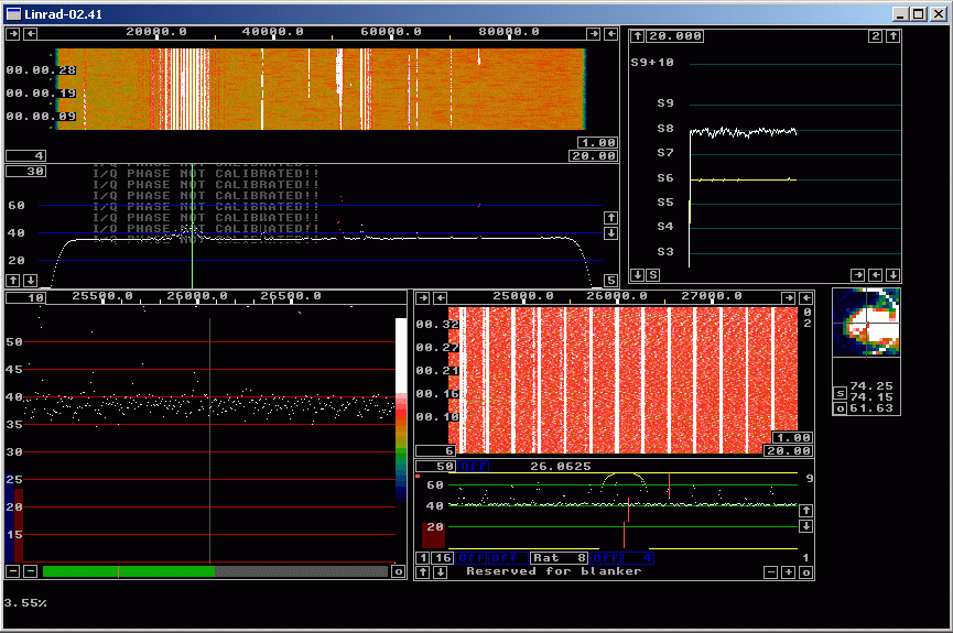
Fig 6.No blanker, no spur removal. Input is 20mnoisel.wav and the calibration file is produced from the 20mcalpul.wav file. | |
|
In figure 7, the noise blanker is enabled and the noise floor
is about 15 dB lower.
In figure 8, both the noise blanker and the automatic spur removal
is running.
The settings for the spur removal is aggressive,
the time constant is only 0.2 seconds.
Figure 9 shows the spur at 14.004644 MHz at high resolution.
It should be pretty obvious that this spur can not be
removed with a very narrow notch and that is the
reason for using aggressive notch parameters that could
destroy CW signals.
SSB should not be affected though.
| |
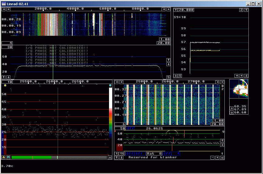
Fig 7. Blanker enabled, but no spur removal. | |
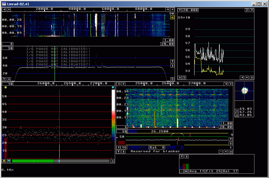
Fig 8. Both blanker and spur removal running. | |
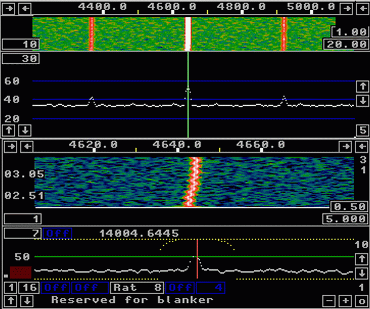
Fig 9. This spur needs a rather wide notch! | |
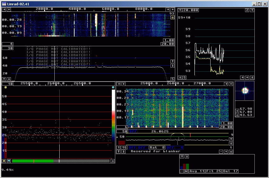
Fig 10. Here the time constant for the spur removal is 0.8 seconds. | |
A signal processing challenge.The file 20mnoise1.wav that can be downloaded from this page contains interference pulses as well as weak and strong CW signals. These signals are of particular interest:Call Freq Real Freq Peak level unkn 51.44kHz 14028.44kHz 80 dB W5ZR 50.91kHz 14027.91kHz 84 dB OK1HB 48.74kHz 14025.74kHz 44 dB The signal of OK1HB is weak and does not last long. It is subjected to QSB down to the noise floor which is at 26 dB RMS in a bandwidth of 20 Hz, the optimum bandwidth for this signal. The maximum S/N is 18dB in 20 Hz, corresponding to -3dB in SSB bandwidth. The signal of OK1HB is well visible in all main waterfall graphs above where the blanker is enabled despite the fact that the waterfall is 96 kHz wide in only 512 pixels. Download the file 20mnoise1.zip (9546443 bytes) Unpack it and run it with your favourite SDR software, compare the visibility in the waterfall with a similar total width as abowe (192 kHz = 1024 pixels) Listen and try to find out which station OK1HB is calling. the file can be played in Linrad, Winrad, WRplus, HDSDR, Rocky, Spectravue and perhaps other SDR software. By use of sim2powersdr.exe (6656 bytes) which has to be placed in the same directory as 20mnoise1.wav and the command sim2powersdr 20mnoise1.wav the file is converted to powersdr-20mnoise1.wav which will work with PowerSDR. The normal loudspeaker output from Linrad ok1hb.mp3 (239908 bytes) allows copying of both transmit periods despite the strong level of the two nearby stations during the second transmission. In the processing mode coh2, where Linrad uses the carrier of the keyed signal to detect in-phase and out-of-phase components within the 20 Hz passband, copy is a little easier. The noise is split equally between I and Q but the signal is present almost exclusively in I. Listen to this file ok1hb_coh2.mp3 (241370 bytes) with stereo head-phones. In situations where the carrier is not stable enough, too weak or if a long time delay is not acceptable, the coh2 mode will fail and put the signal in Q occasionally. With stereo head-phones, one will hear it anyway. The signal will have a fixed phase relation between both ears and seemingly come from one direction while the noise will have random phases and seem to come from all directions. In the coh2 file, S/N is nearly 3 dB better in the I channel as compared to the normal loudspeaker output. When coherent processing is sucessful, selecting the coh3 mode will send the I signal to both ears. The signal is sent only when the signal is in phase, but not when it is 180 degrees out of phase. With noise only, the RMS power is reduced by another 3 dB this way, but the noise itself becomes a keyed signal. Here is the sequence in coh3 mode: ok1hb_coh3.mp3 (238079 bytes) | |

Fig 11. OK1HB on 48.737 kHz. The final 'B' of the second transmission is visible in the S-meter graph. | |
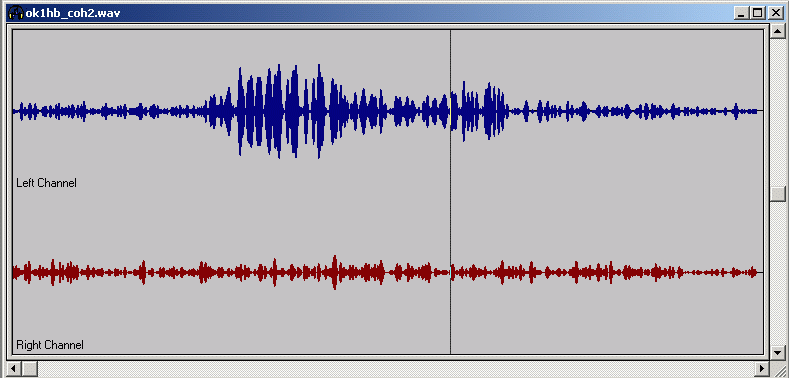
Fig 12. The middle part of ok1hb_coh2.wav as seen with a wave file editor. The Linrad AFC was sucessful in finding the correct frequency and phase. Very little of the signal is in Q. | |
| To SM 5 BSZ Main Page |