Check this link
Correct for amplitude and phase errors in a
direct conversion receiver.
for more recent information.
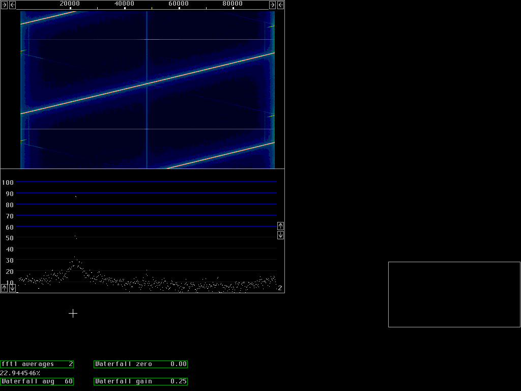
Typical performance of uncompensated direct conversion receiverUsing 1% standard components for the IQ mixer and the anti alias filters the spur suppression is typically around 30 to 40dB. Fig.1 shows a signal that is sweeping slowly across the receiver passband. |

The spur balancing routineThe spur is much smaller than the main signal. As it turns out there is a fixed phase and amplitude relation between the spur and the main signal and therefore the spur can be cancelled easily.After having completed the first fft one more loop is added in the make_fft1() routine in which a small fraction of the spur frequency is added to each frequency. The amplitude and phase of this small fraction is determined by a separate calibration routine. The first screen of the spur balancing routine is shown in fig.2. below. A stable signal generator is connected at the antenna input. The signal level has to be high enough, but it must not saturate the A/D converters - otherwise a warning message will be displayed and no data accumulated. |

|
When most of the segments are green and the operator has pressed "U"
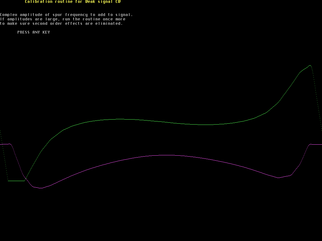
the screen of fig.3 is shown.
This screen is the complex amplitude of the spur frequency that has
to be added to the signal frequency to remove the spur.
If the routine is run one or more times before this screen shows
the amount to add in addition to previously determined values.
To get very good spur suppression the balancing routine has
to be run two or three times.
|

|
How many segments to split the frequency range in depends on the
hardware - how fast the amplitude and phase errors change with
frequency.
With many enough segments and a high quality (low noise) signal
generator the spur can be eliminated completely.
Temperature stability of the analog circuitry may limit the
practically achievable attenuation, something that future
experience will show.
Fig. 4 below is produced exactly as fig. 1 - but after running the calibration routine (with a noisy oscillator, a Tektronix TR503). The spur is suppressed by about 70dB and is almost invisible. |
