Transmitter testing with Linrad in the time domainWith Linrad-01.21 a timedomain oscilloscope showing the RF envelope was introduced. The IC706MKIIG produces very strong keying clicks on HF bands, particularly when run at reduced power. Fig 1 shows the spectrum when I have hand keyed an IC706MKIIG at normal speed with a power setting of "7". It is obvious from the spectrum that something is wrong. |

|
|
Fig.1. The spectrum of a hand keyed IC706MKIIG. The frequency is 7.097 MHz and the power setting is "7" The keying clicks have pronounced maxima at multiples of about 5kHz frequency offset. The spectrum looks like the spectrum of an AM signal. The time domain signal, the RF envelope contains all the information about AM modulation. Fig. 2 shows the envelope while I have keyed my own call sign SM5BSZ at a normal hand keying speed. |

|
|
Fig.2. The RF envelope of a hand keyed IC706MKIIG operated like in fig.1. The x-scale is 283 which means that the sampling rate is 96kHz/283 or about 340 Hz. The entire graph of 1024 pixels corresponds to 3 seconds. The green curve is channel 1 into which the signal is sent. The magenta curve is channel 2. The leakage from channel 1 into channel 2 is about 3% or -30dB. Fig. 2 does not have the time resolution to show anything of interest. In the oscilloscope mode, Linrad works as a conventional digital oscilloscope so the data of figure 2 was stored in memory. Fig. 3 shows the same sequence at an increased sampling rate. |

|
|
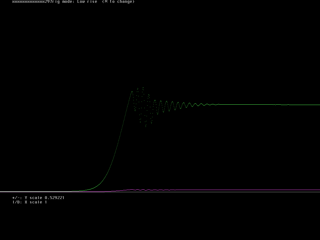
Fig.3. The same data as in fig. 2 at an expanded time scale. The x-scale is 60 which means that the sampling rate is 96kHz/60 or about 1.6 kHz. It is clear from fig. 3 that something happens on the rising edge when the key is pressed, but there is no indication of any problem at the falling edge when the key is released. Fig. 4 to fig. 7 show the rising edges of the three dits of the S and the rising edge of the first dash of the M at maximum expansion of the time scale. |

|
|
Fig.4. The same data as in fig. 2 at an expanded time scale. This is the rising edge of the first dot. The x-scale is 1 which means that the sampling rate is 96kHz. |

|
|
Fig.5. The same data as in fig. 2 at an expanded time scale. This is the rising edge of the second dot. The x-scale is 1 which means that the sampling rate is 96kHz. |

|
|
Fig.6. The same data as in fig. 2 at an expanded time scale. This is the rising edge of the third dot. The x-scale is 1 which means that the sampling rate is 96kHz. |

|
|
Fig.7. The same data as in fig. 2 at an expanded time scale. This is the rising edge of the first dash. The x-scale is 1 which means that the sampling rate is 96kHz. It is immediately clear from figures 3 to 6 that the IC706MKIIG has a far too short time constant for the ALC release. The small pause between letters is long enough for the ALC voltage to nearly disappear due to the far too short time constant. The mere fact that oscillations occur is also an indication of the same problem. The shape of the keying would be quite good if the actions of the ALC were eliminated, something one can do for example by feeding a constant voltage into the ALC. Figure 8 shows the falling edge. It is identical everywhere. |

|
|
Fig.8. The same data as in fig. 2 at an expanded time scale. The falling edges look like this. The x-scale is 1 which means that the sampling rate is 96kHz. To SM 5 BSZ Main Page |