
Homebrew Software to Control Multiple HPSDR Radios
by W3SZ 2/27/2015
C# application running under Windows XP. It will control up to 8 HPSDR radios are simultaneously . It is interfaced with N1MM Logger Plus
One of my interests in Amateur Radio is designing and implementing single-user multiband contest station setups. My specific area of interest is in systems for the VHF/UHF/microwave contests, covering the Amateur bands from 50 MHz through 24 GHz, inclusive. I want to be able to run multiple software defined radios [SDRs] from a single computer, using the same screen/keyboard/mouse and also the same microphone/footswitch/speaker for all of them. The goal is to have individual, always-on bandscopes that simultaneously view the 50, 144, 222, 432, 903, and 1296 MHz bands, as well as a selected microwave band on a seventh SDR that covers each of the bands 2.3 through 24 GHz inclusive, to have another bandscope/controller for the HF bands, and to have the "radio be the bandscope". This minimizes the operational complexity of the system, by allowing the operator to instantly switch the "active radio" frequency to be that frequency on which an interesting signal has been spotted, on any one of the eight "bands", by clicking on the appropriate radio/bandscope. Also, I want all eight SDRs to appear as a single radio to the N1MM+ logging program, and for N1MM+ to automatically select the correct SDR when the operator switches bands within the N1MM+ program.
The paradigm is to have 8 radio GUI-bandscopes, one for each "band" as defined above. When not selected by the operator, the individual bandscopes appear as smaller windows, as you can see in the image above. When selected as either [1] the main radio or [2] the aux (liaison) radio, the selected bandscope will enlarge and move to the preselected screen position for the main or aux radio, depending upon which spot was selected for that band.
The software I've put together to accomplish this is based on the fantastic KissKonsole software by Phil Harman, VK6PH, which works with the excellent HPSDR hardware. I wrote/modified/compiled the software using Visual Studio 2013, which is now a free product. The software was targeted at .NET Framework 4.
With the client software I wrote, there are 3 ways for the operator to select which band (radio) is active as either the main or the aux radio. The first way of selecting a band for operation is by mouse-clicking on the spectrum/waterfall of the small bandscope for a given band. Left-clicking will move the radio to the main radio position. Right-clicking will move the radio to the aux radio position.
The bands to be selected as main and aux radios can also be selected from the Main Controller Bar, which as you can
see in the image above, is placed at the bottom of the screen. It is shown
below.

Clicking a "Radiobutton" for a band on the row of the bar labeled "Main" will bring that radio to the Main Radio position on the screen, and the expanded radio window thus exposed gives access to all of the main radio controls. This action will also make this band the main radio in N1MM+. Similarly, clicking a "Radiobutton" for a band on the "Aux" row of the bar will bring that radio to the Aux Radio position on the screen, and the expanded radio window thus exposed gives access to all of the aux radio controls. This action will also make this band the aux radio in N1MM+.
The third way of moving a radio to the main or auxiliary radio position is through N1MM+. Typing a frequency into the main radio entry window of N1MM+ will select the appropriate radio and place it in the main radio position on the screen and put it on that frequency. Similarly, typing a frequency into the aux radio entry window of N1MM+ will select the appropriate radio and place it in the aux radio position on the screen and put it on that frequency.
As you can see above, on the right side of the Main Controller Bar are Radiobuttons on both the Main Radio and the Aux Radio rows for "L Foot" (the left footswitch), "R Foot" (the right footswitch), the Microphone, the (CW) Key, and two audio channels ("Audio 1" and "Audio 2"). If the "L Foot" button on the Main Radio row is selected, then the left footswitch will be assigned to whichever radio is assigned as the main radio. Similarly for the "R Foot", "Mic", "Key", and the two audio channels. Of course, if the "L Foot" Radiobutton on the Aux Radio row is selected, then the left footswitch will be assigned to whichever radio is assigned as Aux Radio. For the operator using N1MM+, the experience is that of having a single radio with always-on bandscopes for all of the bands described above that covers every band from 50 MHz through 24 GHz, inclusive, with automatic bandswitching not only of antennas, but also of footswitches, microphone, key, and receive audio. The Main Controller Bar also allows the operator to mute either audio channel, or both [or none].
I placed a video on YouTube that shows me running the client software through its paces.
The video is here. It is silent.
Basically, the design of the software does the following:
1. Splits
KissKonsole (written by Phil Harman VK6PH with important contributions by
others) into a server and a client, designed for VHF and microwave use.
2.
The client controls multiple [up to 8 as configured] HPSDR Radios/servers:
50 MHz
144 MHz
222 MHz
432 MHz
903 MHz
1296 MHz
2-3-5-10-24
GHz
HF
3. The server sends Spectrum/Waterfall data to client
4. The
server sends CW sidetone data to client
5. The client controls the server, to
provide remote control [via ethernet] of all important radio functions
6. The
client interfaces with N1MM+, appearing to N1MM+ as one multiband radio covering
HF through 24 GHz
7. The client switches CW key/mic/2 footswitches/2 receive
audio channels between radios, using a separate USB hardware device
8. N1MM+
switches antennas among radios based on band data sent to N1MM+ from client
9. Added Adjustable FFT size 4096 to 524288 added to server
10.
Added "Wisdom" optimization of FFT calculations, performed first time program is
run
11. Added multiple waterfall palettes to client
12. Added computer
receive audio to server so that audio can be obtained without connection to
radio headphone jack, via Windows sound
13. Added zoom of spectrum/waterfall
to both server and client
14. Added CW sidetone to to both client and server.
CW works with hand key or with typed CW from N1MM+, via WinKey.
This system replaces the OSX system that I had previously designed, and which I have used for a number of years. That system is described here
The radio hardware used with the current system is very similar to that used with the older system:
50 MHz SDR: HPSDR Hermes with the server running on a 3.2 GHz Pentium 4
144 MHz SDR: Elecraft K3 with an HPSDR bandscope running on a 3.1 GHz Core 2 Duo
222 MHz SDR: HPSDR Atlas/Ozy/Penelope/Mercury stack running on a 3.1 GHz Core 2 Duo
432 MHz SDR: HPSDR Atlas/Ozy/Penelope/Mercury stack running on a 3.1 GHz Core 2 Duo
903 MHz SDR: HPSDR Atlas/Ozy/Penelope/Mercury stack running on a 3.1 GHz Core 2 Duo
1296 MHz SDR: HPSDR Atlas/Ozy/Penelope/Mercury stack running on a 3.1 GHz Core 2 Duo
2.3-24 GHz SDR: HPSDR Atlas/Ozy/Penelope/Mercury stack running on a 3.1 GHz Core 2 Duo

The individual HPSDR computers running the server portion of the software are linked to the client/controller portion of the software using a Gigabit Ethernet switch, and all of the servers are running Gigabit links with jumbo frames capability. This bandwidth capacity was necessary with the old OSX system, but is far greater than is needed with the new system. With the new system I only need to run a 100 Mbps NIC on the client computer, and only 0.22% of the 100 Mbps bandwidth is used by the system, as you can see on the left. The Local Area Connection 3 is not in use.
 The
network connections are set up using setup menus from the client software and
each of the servers. The setup menu on the left is one of three available
from the Main Controller Bar of the client software. With this page the
user sets the IP address for the HPSDR for each band. The user also sets
the COM ports used to communicate with the HPSDR Controller hardware that will
be described below, as well as the virtual com ports used to communicate with
N1MM+.
The
network connections are set up using setup menus from the client software and
each of the servers. The setup menu on the left is one of three available
from the Main Controller Bar of the client software. With this page the
user sets the IP address for the HPSDR for each band. The user also sets
the COM ports used to communicate with the HPSDR Controller hardware that will
be described below, as well as the virtual com ports used to communicate with
N1MM+.
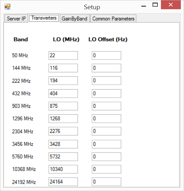
The second setup screen available from the Main Controller Bar of the client software is shown on the left. It allows the user to set the LO frequency and offset for each transverter.
The third setup screen, not shown here, allows the user to set the transmitter Band Gain for each HF, VHF, UHF, and microwave band.

The window on the left shows the first server-side setup tab. On the right it has additions to the original KissKonsole software to allow setting the IP address of the client computer, to specify the band assigned to the server by the client software, and to set the FFT size to be used for the bandscope and spectrum display.
For switching of ancillary hardware, this system uses the same Parallax Propeller USB Proto Boards that I used for the original OSX-based control system, running custom Spin applications on the Propellers to set the assignments of the footswitch, microphone, CW keys and receive audio channels to the main and aux HPSDR radios. A USB connection is used between the client computer and the Parallax Propellers. One Propeller (lets call it the RadioManager) is used to control the footswitches, mic, and key, and a second Propeller (lets call it the AudioManager) controls the receive audio channels.
Each of the RadioManager Propeller's 28 outputs drives, through a 22K resistor, a 2N2222a which controls a G6L-1P-DC12 relay that provides the necessary switching between the radios of the left and right footswitches, microphone, and CW key [4 banks of 7 outputs each, to connect Left Footswitch, Right Footswitch, Microphone, and CW Key each to one of the 7 radios (the HF radio is not controlled by this device)]. A single small printed circuit board from Express PCB is used for each bank of 7 outputs. The ExpressPCB PCB file for the RadioManager boards is here. The ExpressPCB schematic file for the RadioManager boards is here.
I made the audio control interface a separate hardware controller because a single Propeller did not have enough outputs to handle of the the control channels. The custom Spin application on the AudioManager Propeller drives, through 22K resistors, 2N2222a transistors that control 3 banks of 7 G5V-2-H1-DC12 DPDT 12VDC relays each, so that I can switch each of the 7 radios to any one of 3 audio output ports. There is one "extra" relay bank available for expansion to 7 radios. The Express PCB boards used for this task are similar to, but not identical to, those used for the input device switching described above. Each of the two audio channels can be independently muted, as well. The ExpressPCB PCB file for the Audio Controller boards is here. The ExpressPCB schematic file for the Audio Controller boards is here.
To initiate a session, each HPSDR radio and its associated computer is powered up and a KissKonsole server is started on the computer associated with each HPSDR radio. These computers are "headless" and have no monitor, keyboard, or mouse. If necessary, they can each be accessed via VNC, but there is no VNC used during system operation, greatly reducing the required network bandwidth. The client software and N1MM+ are started on the control computer. One can then begin running the bands.
Below is a photo taken during construction of the layout of the controller with the 2 Parallax Propellers at the top and the 4 RadioManager boards with small beige relays, and the 3 Audio Controller boards with the larger black relays. The ExpressPCB PCB file for the RadioManager boards is here. The ExpressPCB PCB file for the Audio Controller boards is here. The ExpressPCB schematic file for the RadioManager boards is here. The ExpressPCB schematic file for the Audio Controller boards is here.

Below is how the Controller looks when completely wired.

Below is a front view of the finished product.

Below is a view of the rear panel.

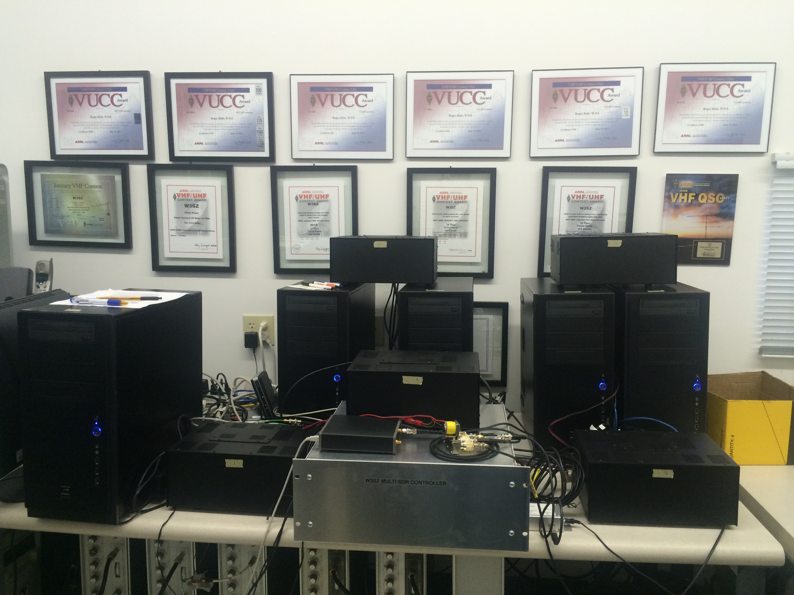
Below is a picture of the SDR controller and five of the six computers with their associated HPSDR units. The sixth computer is off-screen.
This software is not intended to be used as is by other operators, as it was designed/built to be used at my station, but the source code is provided with the hope that it may help others in their software building efforts. Below are links from which you can download the source code.
Client
4.7 MB
Server 13.3 MB
The code was compiled with Visual Studio 2013, and
Framework 4.
Copyright © 1997-2015 COPYRIGHT Roger Rehr W3SZ. All Rights Reserved
Brought to you by the folks at W3SZ