Homebrew
Software
to Control Multiple HPSDR Radios either Locally or from a Remote
Location
by W3SZ
6/27/2015 most recently updated 3/24/2024
C#
application
running under Windows 10. It will control up to 8 HPSDR radios
simultaneously. It is interfaced with N1MM Logger Plus.
My main interests
in Amateur Radio are VHF/UHF/Microwave weak signal operations, and
Software Defined Radios. This project involved setting up an SDR
system so that the system appears to the operator as a single radio
(well, two radios, actually: one Main Radio and one Liaison
[Auxiliary] Radio, operating so one can both transmit and receive on
two bands at once) covering all of the Amateur bands from 50 MHz
through 24 GHz, inclusive.
The goal of the
project is to be able to run, either from a single local computer or
remotely via the ethernet, multiple software defined radios
[SDRs]using the same screen/keyboard/mouse and also the same
microphone/footswitch/speaker for all of them, without the need for
any manual bandswitching. The goal is to have individual, always-on
bandscopes that simultaneously view the 50, 144, 222, 432, 903, and
1296 MHz bands, as well as a selected microwave band on a seventh SDR
that covers each of the bands 2.3 through 24 GHz inclusive, to have
another bandscope/controller for the HF bands, and to have the "radio
be the bandscope". This minimizes the operational complexity of the
system, by allowing the operator to instantly switch the "active
radio" frequency to be that frequency on which an interesting signal
has been spotted, on any one of the eight "bands", by clicking on the
appropriate radio/bandscope. Also, as noted above all eight SDRs are
appear as two radios (SO2R-style, but with the capability of both
transmitting and receiving on two bands simultaneously) to the N1MM+
logging program, and for N1MM+ to automatically select the correct SDR
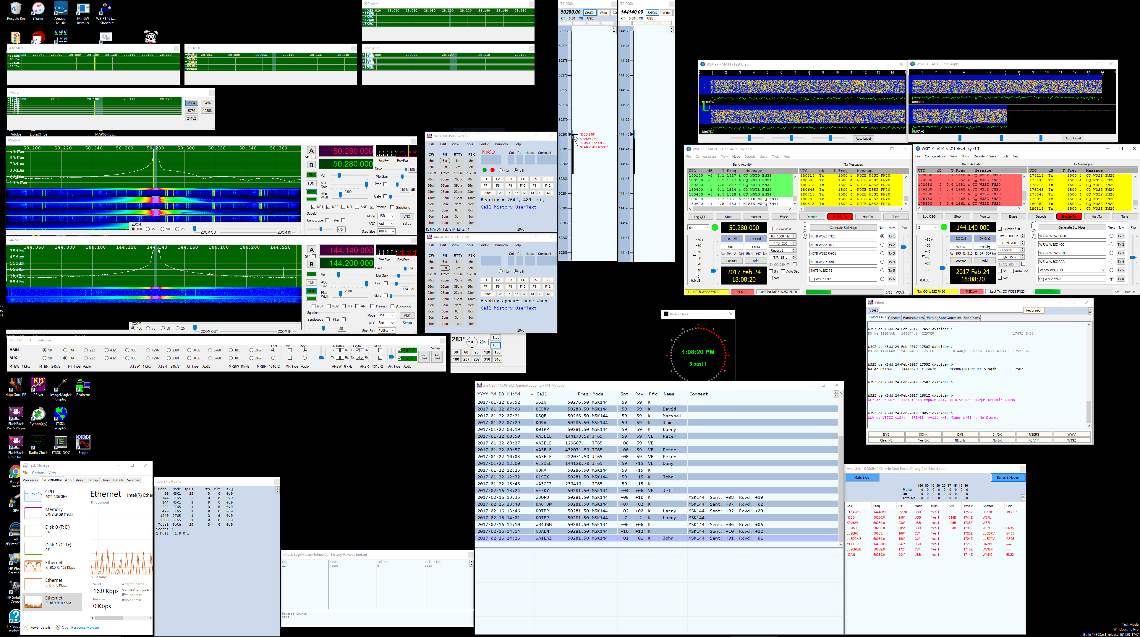
when the operator switches bands within the N1MM+ program. The screen
grab above shows the system in operation. 144 MHz is selected as the
main radio, and 1296 MHz is selected as the liaison (auxiliary) radio,
and these bands are displayed as large, full-function windows. The
N1MM+ entry window for each of these two radios is situated
immediately to the right of the corresponding radio window. The other
radio bands are not selected, and so they are being monitored in the
smaller bandscopes visible on the screen above the two selected
radios.
So the paradigm
is to have 8 radio GUI-bandscopes, one for each "band" as defined
above. When not selected by the operator, the individual bandscopes,
as just noted, appear as smaller windows as you have seen in the image
above. When selected as either [1] the main radio or [2] the aux
(liaison) radio, the selected bandscope will enlarge and move to the
preselected screen position for the main or aux radio, depending upon
which spot was selected for that band, as seen above, and all of the
necessary radio controls will appear for that radio on its enlarged
GUI.
This software can
be used either with the operator at the location of the radios or with
the operator at a remote location connected to the radio site by an
ethernet link, either wired or wireless. In either case, the operator
interacts with the client software which interacts with the server
software for each hardware radio.
The
software
I've put together to accomplish this is based on the fantastic KISS
Konsole software by Phil Harman, VK6PH, which works with the
excellent HPSDR hardware. Phil is
one of the gurus and leaders of the HPSDR project. I
wrote/modified/compiled the software using Visual
Studio
2013 (and later, Visual Studio 2015) which is now a free product.
The software was initially targeted at .NET Framework 4, and was begun
on Windows XP. But because there were features that I wanted to use that
required Framework 4.5, the project was moved to Windows 7 and then 8.1, then 10,
and finally Windows 11. It will no longer run on Windows XP, but will
run on Windows 7, 8, and 8.1, 10, and 11.
With the client
software I wrote, there are 3 ways for the operator to select which
band (radio) is active as either the main or the aux radio. The first
way of selecting a band for operation is by mouse-clicking on the
spectrum/waterfall of the small bandscope for a given band.
Left-clicking will move the radio to the main radio position.
Right-clicking will move the radio to the aux radio position.
The bands to be
selected as main and aux radios can also be selected from the Main
Controller Bar, which as you can see in the image above, is placed at
the bottom of the screen. It is shown in more detail below.

Clicking a
"Radiobutton" for a band on the row of the bar labeled "Main" will
bring that radio to the Main Radio position on the screen, and the
expanded radio window thus exposed gives access to all of the main
radio controls. This action will also make this band the main radio in
N1MM+. Similarly, clicking a "Radiobutton" for a band on the "Aux" row
of the bar will bring that radio to the Aux Radio position on the
screen, and the expanded radio window thus exposed gives access to all
of the aux radio controls. This action will also make this band the
aux radio in N1MM+.
The third way of
moving a radio to the main or auxiliary radio position is through
N1MM+. Typing a frequency into the main radio entry window of N1MM+
will select the appropriate radio and place it in the main radio
position on the screen and put it on that frequency. Similarly, typing
a frequency into the aux radio entry window of N1MM+ will select the
appropriate radio and place it in the aux radio position on the screen
and put it on that frequency.
As you can see
above, on the right side of the Main Controller Bar are Radiobuttons
in both the Main Radio and the Aux Radio rows for "L Foot" (the
footswitch), the Microphone, and the (CW) Key. If the "L Foot"
button on the Main Radio row is selected, then the footswitch will be
assigned to whichever radio is assigned as the main radio. Similarly
for the "Mic" and "Key". Of course, if the "L Foot" Radiobutton on the
Aux Radio row is selected, then the footswitch will be assigned to
whichever radio is assigned as Aux Radio. For the operator using
N1MM+, the experience is that of having a single radio with always-on
bandscopes for all of the bands described above that covers every band
from 50 MHz through 24 GHz, inclusive, with automatic bandswitching
not only of antennas, but also of footswitch, microphone, key, and
receive audio. To the right of the "Key" Radiobuttons are additional
controls. The leftmost trackbar sets the audio level for the transmit
audio monitor. To the right of this trackbar is a GroupBox labeled
"N1MM+". Checking either the Main or the Aux "Tx" box will sent
N1MM-generated audio to the respective radio. Checking either the Main
or the Aux (or both) Rx box will send the receive audio from the
respective radio[s] to the N1MM+ add-on QSOrder. In this manner all
contest audio or specific QSO audio or both can be saved. To the right
of the N1MM GroupBox is the Digital Groupbox. The checkboxes serve
similar purposes to those described for N1MM, but in this case they
send received audio from the selected radio to a digital program such
as WSJT-X, WSJT, etc. and they receive transmit audio from WSJT-X or
WSJT, etc. and send it to the appropriate radio. Each radio can
be connected to a separate instance of WSJT-X, and this software can
transmit simultaneously on the Main Radio using one instance of
WSJT-X, and on the Aux Radio using another instance of WSJT-X.
The illustration at the top of this page shows the software
simultaneously calling CQ using MSK144 on both 50 MHz and 144 MHz. To
the right of the Digital GroupBox is a GroupBox labeled "Mute".
Clicking the appropriate checkbox in this GroupBox will mute the
speaker/headphone received audio for the selected radio[s]. It will
have no effect on audio being sent to N1MM+ or to WSJT-X, WSJT, etc.
To the right of the Mute GroupBox is a trackbar for adjusting the
audio level of the Main and Aux radios. Additional volume controls are
provided on each radio, but this provides a convenient place to adjust
the global received audio level. To the right of this trackbar
are checkboxes to activate CAT control for the Main and Aux Radios,
and to the right of those controls are buttons to reset the Mic and
Receive audio steams. The Setup button is above one of these
buttons, and brings up the setup form that will be described
below. In this setup form the bands to be displayed can be
selected and many other parameters can be selected or changed. If a
band has not been selected for display, then it will not appear on the
control bar, and its radio GUI will not be displayed.
I placed a video
on YouTube that shows me running the client software through its
paces. The software has been updated and expanded since this video was
made, so this video does not show all of the features currently
available with this software.
The
video
is here.
Basically,
this
software makes the following changes/additions to the original KISS
Konsole software:
1. Splits KISS Konsole (written by Phil Harman VK6PH with important
contributions by others) into a server and a client, designed for
multiband VHF and microwave use.
2. The client controls multiple [up to 8 as configured] HPSDR
Radios/servers:
50 MHz
144 MHz
222 MHz
432 MHz
903 MHz
1296 MHz
2-3-5-10-24 GHz
HF.
3. The server sends Spectrum/Waterfall/receive audio data to client.
4. The client controls the server, to provide remote control [via
ethernet] of all important radio functions.
5. The client interfaces with N1MM+, appearing to N1MM+ as one multiband
radio covering HF through 24 GHz.
6. The client uses either a wired or wireless ethernet connection to
send CW key input, microphone input, footswitch input from the computer
at operator's site running the client software to the radio servers at
the remote site. Bandwidth required for both microphone audio and
receive audio is substantially reduced through use of the Opus
codec.
7. The 2-3-5-10-24 GHz radio server switches transverters-antenna
combinations among radios for these bands based on band data sent to
this server by the client.
8. Added Adjustable FFT sizes for the graphic displays from 4096 to
524288 to server.
9. Increased receiver audio FFT size from 2048 to 32768 to provide for
steeper filter skirts.
10. Added "Wisdom" optimization of FFT calculations, which is performed
the first time program is run.
11. Added multiple waterfall palette options to client.
12. Added computer receive audio so that audio can be obtained
without connection to radio headphone jack, via Windows sound (available
at either the server computer if the server is used in stand-alone
fashion as it might be for testing/single-band operation, or at the
remote computer if, as usual, the client software is used).
13. Added zoom of spectrum/waterfall to both server and client.
14. Added CW sidetone to to both client and server. CW input can be
either from a straight key or WinKeyer output, or with typed CW from
N1MM+ (which usesWinKeyer).
15.Up/Down arrows will move frequency up/down by "Step Size". This
allows the ShuttlePRO
v2 to act as a "knob" for frequency control.
16. Step Size can also be set from the ShuttlePRO. The software is set
up with the following key assignments: a=1 Hz; b=10 Hz; c=100 Hz; d=1
kHz.
17. Mode can be set from the ShuttlePRO. The software is set up with the
following key assignments: e=FM; f=USB; g=LSB; h=CWU; i=CWL.
18. The client will "kill" transmit automatically if , while
transmitting, either the Main or Aux radio is deslected from its Main or
Aux position. This feature is included to make the system more "fool
resistant", this necessity becoming apparent as a result of extensive
contest use, sometimes after little or no sleep for 24 hours or more.
19.Direct digital audio input from N1MM+ or other contest logging
programs is provided, as is digital PTT. Ability to send digital audio
from the HPSDR radios directly to N1MM+/QSOrder is provided.
20. Direct digital audio capabilities to and from digital programs such
as WSJT-X, WSJT, etc. and digital PTT from these programs is
provided. The Main and Aux Radios can each run a separate instance
of WSJT-X, and both can transmit simultaneously if desired.
21. Monitoring of transmit audio from the microphone, N1MM+, WSJT-X,
etc. is provided. Also provided is monitoring, at the client site, of
the output of the transmitter at the remote site via the receiver
portion of the server program, whose audio is sent to the client program
via the ethernet as noted above (full duplex mode).
22. Addition of frequency-domain frequency-specific AGC, because the usual time-domain AGC is
poorly suited to use with digital signals, and because some AGC is unfortunately necessary with
the nowadays usual combination of extremely strong local signals and very weak distant signals
in the same audio passband.
The
radio
and computer hardware used with the current system is similar but not
identical to that used with the older system that this system replaced
and which is no longer in use:
The
client
software runs on a 4.2 GHz I7-5770K when I am operating from the
remote location where the radios are. At home, my main machine is an
I7-4790K running at 4.0 GHz, and so I use that to run the client
software as a matter of convenience when operating from home, via a
dedicated wireless link.
50
MHz
SDR: HPSDR Atlas/Ozy/Penelope/Mercury with the server running on a 3.2
GHz I5-4460
144 MHz SDR:HPSDR Atlas/Ozy/Penelope/Mercury stack running on a 3.1
GHz Core 2 Duo
222 MHz SDR: HPSDR Atlas/Ozy/Penelope/Mercury stack running on a 3.1
GHz Core 2 Duo
432 MHz SDR: HPSDR HPSDR Atlas/Ozy/Penelope/Mercury running on a 3.1
GHz Core 2 Duo
903 MHz SDR: HPSDR Atlas/Ozy/Penelope/Mercury stack running on a 3.6
GHz Intel I3
1296 MHz SDR: HPSDR Atlas/Ozy/Penelope/Mercury stack running on a 3.1
GHz Core 2 Duo
2.3-24 GHz SDR: HPSDR Atlas/Ozy/Penelope/Mercury stack running on a
3.1 GHz Core 2 Duo
I
used to run HPSDR Hermes units on 50 and 432 MHz, but the Hermes was
extremely glitch-prone, whereas the stacks that I am currently running
are free from this problem.
 The
individual HPSDR computers running the server portion of the software
are linked to the client/controller portion of the software using a
Gigabit Ethernet switch, and all of the servers are running Gigabit
links with jumbo frames capability. This bandwidth capacity was
necessary with the old OSX system, but is far greater than is needed
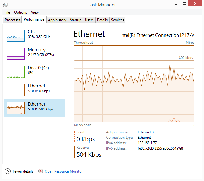
with the new system. With the new system I only need to run a 100 Mbps
NIC on the client computer, and only 0.5% of the 100 Mbps bandwidth is
used by the system, as you can see in the image on the left. This low
bandwidth was achieved by using the Opus codec to substantially reduce
the streaming bandwidth. With two-radio receive audio streaming without
the use of Opus, the bandwidth used is 2.2-2.5% (2.2-2.5 Mbps). With the
addition of the Opus codec, each audio channel takes less than 30 kbps,
and the total receive audio bandwidth for two radios is only 50 kbps, on
the order of 2% of the bandwidth without the use of the codec. In fact,
when the Opus codec is used, the total ethernet bandwidth for the entire
program with its control signals, 7 bandscopes, and simultaneous two
radio receive audio streaming is only 0.5 Mpbs, as noted above and as
shown in the illustration above. The Opus codec also provides
Forward Error Correction (FEC) of the audio streams.
The
individual HPSDR computers running the server portion of the software
are linked to the client/controller portion of the software using a
Gigabit Ethernet switch, and all of the servers are running Gigabit
links with jumbo frames capability. This bandwidth capacity was
necessary with the old OSX system, but is far greater than is needed
with the new system. With the new system I only need to run a 100 Mbps
NIC on the client computer, and only 0.5% of the 100 Mbps bandwidth is
used by the system, as you can see in the image on the left. This low
bandwidth was achieved by using the Opus codec to substantially reduce
the streaming bandwidth. With two-radio receive audio streaming without
the use of Opus, the bandwidth used is 2.2-2.5% (2.2-2.5 Mbps). With the
addition of the Opus codec, each audio channel takes less than 30 kbps,
and the total receive audio bandwidth for two radios is only 50 kbps, on
the order of 2% of the bandwidth without the use of the codec. In fact,
when the Opus codec is used, the total ethernet bandwidth for the entire
program with its control signals, 7 bandscopes, and simultaneous two
radio receive audio streaming is only 0.5 Mpbs, as noted above and as
shown in the illustration above. The Opus codec also provides
Forward Error Correction (FEC) of the audio streams.
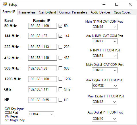 The
network connections between the client and server are set up using
setup menus contained in the client and server software. The setup
menu shown here and labeled "Server IP" is one of six menu pages
available from the Main Controller Bar of the client software. With
this page the user [1] sets the IP address for the HPSDR-server for
each band (radio), [2] selects the radios that will be displayed,
and [3] assigns the COM ports that are used for various functions.
Assignment of the IP addresses for each radio server is
self-explanatory. The virtual COM ports provide for WinKeyer
Control, CW Key/Keyer and Manual PTT input, N1MM+ CAT control for
the main and auxiliary radios, WSJT-X CAT control for the main and
auxiliary radios, and PTT control from N1MM+ as well as the WSJT-X
instances associated with the main and auxiliary radios.
The
network connections between the client and server are set up using
setup menus contained in the client and server software. The setup
menu shown here and labeled "Server IP" is one of six menu pages
available from the Main Controller Bar of the client software. With
this page the user [1] sets the IP address for the HPSDR-server for
each band (radio), [2] selects the radios that will be displayed,
and [3] assigns the COM ports that are used for various functions.
Assignment of the IP addresses for each radio server is
self-explanatory. The virtual COM ports provide for WinKeyer
Control, CW Key/Keyer and Manual PTT input, N1MM+ CAT control for
the main and auxiliary radios, WSJT-X CAT control for the main and
auxiliary radios, and PTT control from N1MM+ as well as the WSJT-X
instances associated with the main and auxiliary radios.
 The
second
setup
screen available from the Main Controller Bar of the client software
is labeled "Transverters", as shown here. It allows the user to set
the LO frequency and offset for each transverter. Because my
transverters are GPS-locked on all bands, the LO offset is
consistently zero. The third setup screen, not shown here, allows
the user to set the transmitter Band Gain for each HF, VHF, UHF, and
microwave band. I have a separate, software controlled HP attenuator
that is used to set drive levels and receive attenuation levels
automatically for each band, to provide optimal transmit drive for
each band and a consistent noise floor on receive for each band, and
so the third setup screen is not needed in my current setup. It is
however maintained in case of future need.
The
second
setup
screen available from the Main Controller Bar of the client software
is labeled "Transverters", as shown here. It allows the user to set
the LO frequency and offset for each transverter. Because my
transverters are GPS-locked on all bands, the LO offset is
consistently zero. The third setup screen, not shown here, allows
the user to set the transmitter Band Gain for each HF, VHF, UHF, and
microwave band. I have a separate, software controlled HP attenuator
that is used to set drive levels and receive attenuation levels
automatically for each band, to provide optimal transmit drive for
each band and a consistent noise floor on receive for each band, and
so the third setup screen is not needed in my current setup. It is
however maintained in case of future need.
 The fourth setup screen is used to set the CW
sidetone pitch and volume and to choose the location of the
program "Tight VNC" and the VNC password for the remote radio
servers. On this page the user can also select the waterfall
palette to be used for all radios.
The fourth setup screen is used to set the CW
sidetone pitch and volume and to choose the location of the
program "Tight VNC" and the VNC password for the remote radio
servers. On this page the user can also select the waterfall
palette to be used for all radios.
 The fifth setup page available from the control bar
is used to select the audio devices. There are four input
audio devices to be chosen, and four output audio devices.
The input audio devices are for microphone input, transmit
audio from N1MM+, and transmit audio from WSJT-X or WSJT for
both the main and auxiliary radios. The output audio devices
are for headphones [or speakers], received audio directed to
N1MM+/QSORder for recording, and received audio directed to
WSJT-X or WSJT from both the main and auxiliary radios for
decoding of digital signals.
The fifth setup page available from the control bar
is used to select the audio devices. There are four input
audio devices to be chosen, and four output audio devices.
The input audio devices are for microphone input, transmit
audio from N1MM+, and transmit audio from WSJT-X or WSJT for
both the main and auxiliary radios. The output audio devices
are for headphones [or speakers], received audio directed to
N1MM+/QSORder for recording, and received audio directed to
WSJT-X or WSJT from both the main and auxiliary radios for
decoding of digital signals.
 The sixth setup page
available from the control bar is used to set parameters for
the OPUS encoder/decoder. Separate parameter sets can
be selected for voice and data modes, and for receive and
transmit.
The sixth setup page
available from the control bar is used to set parameters for
the OPUS encoder/decoder. Separate parameter sets can
be selected for voice and data modes, and for receive and
transmit.
In
this example, shown on the right, narrow (4 kHz) bandwidths
are chosen for voice-mode receive and transmit and for
data-mode transmit. Medium bandwidth (6 kHz) is chosen
for data mode receive. Bit rates of 8192/sec are
chosen for voice mode transmit and receive. For data
mode receive a bit rate of 131072/sec is chosen, and a bit
rate of 24576 is chosen for data mode transmit.
Voip-type codecs are chosen for voice mode and audio-type
codecs are chosen for data mode. Each of these
particular choices were informed by testing done at W3SZ.
 There
are
also individual setup menus for each "radio" included in the
client software, which are accessed from the individual band
window for each "radio" when that radio has been selected to be
either the main radio or the aux radio. An example is on the
right. Display spectrum and waterfall parameters can be set, as
well as Sample Rate and FFT Size, and maximum AGC gain.
The "Duplex" check box enables or disables receive audio
while transmtting.
There
are
also individual setup menus for each "radio" included in the
client software, which are accessed from the individual band
window for each "radio" when that radio has been selected to be
either the main radio or the aux radio. An example is on the
right. Display spectrum and waterfall parameters can be set, as
well as Sample Rate and FFT Size, and maximum AGC gain.
The "Duplex" check box enables or disables receive audio
while transmtting.
 The
window
shown
here and labeled "Setupform" is the first server-side
setup tab included in the set of setup menus available for
the server software. My additions to this tab, that were
not present with the original KISS Konsole setup menus,
allow the user to set the IP address of the client
computer, to specify the frequency band assigned to the
server by the client software, to set the FFT size to be
used for the bandscope and spectrum display, to set CW
sidetone pitch and volume, to select whether or not to
route local audio to the local computer, to select the
buffer size to be used for transmit audio, and whether or
not to use ethernet for microphone audio, receive audio,
and CW keying. On the "Display and Opus" tab
additions include the ability to set the Opus Codec
parameters in the same fashion as was shown above for the
client software. On the "Transmitter" tab additions
include the ability to select whether or not to monitor
remote mic audio and if so to adjust its volume, and to
set the default width of the SSB Tx Filter. On the
"Ext Ctrl" tab I added a selection for remote ethernet
control of switching of the microwave transverter-antenna
combinations via an LPT port on the GHz server, and a box
in which to provide the address for that LPT port.
The
window
shown
here and labeled "Setupform" is the first server-side
setup tab included in the set of setup menus available for
the server software. My additions to this tab, that were
not present with the original KISS Konsole setup menus,
allow the user to set the IP address of the client
computer, to specify the frequency band assigned to the
server by the client software, to set the FFT size to be
used for the bandscope and spectrum display, to set CW
sidetone pitch and volume, to select whether or not to
route local audio to the local computer, to select the
buffer size to be used for transmit audio, and whether or
not to use ethernet for microphone audio, receive audio,
and CW keying. On the "Display and Opus" tab
additions include the ability to set the Opus Codec
parameters in the same fashion as was shown above for the
client software. On the "Transmitter" tab additions
include the ability to select whether or not to monitor
remote mic audio and if so to adjust its volume, and to
set the default width of the SSB Tx Filter. On the
"Ext Ctrl" tab I added a selection for remote ethernet
control of switching of the microwave transverter-antenna
combinations via an LPT port on the GHz server, and a box
in which to provide the address for that LPT port.
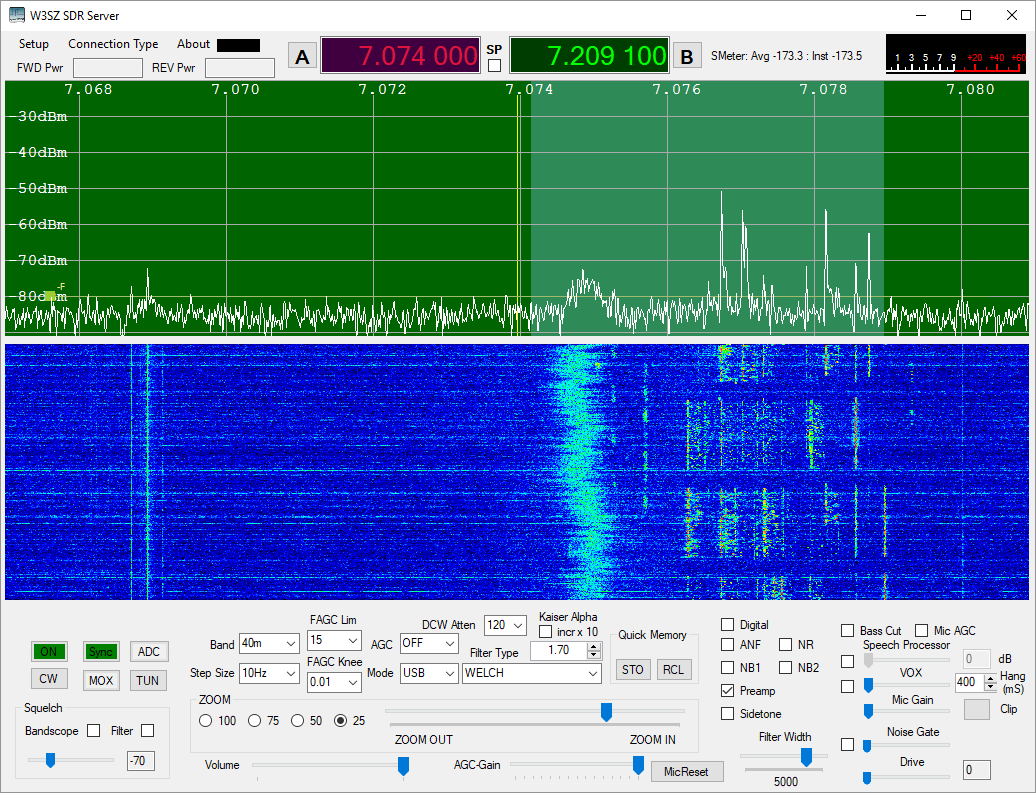
I almost
forgot to show a picture of the server software. Here it is,
with Mercury receiving on 40 meters in the digital portion of the
band. The display is zoomed in somewhat, and the benefits of
a larger FFT are clearly evident. The CW "button" below the
Green "ON" button is an indicator that turns red during the
key down state. It is used for display only and has no input
function.For switching of ancillary hardware, this system
originally used the same Parallax
Propeller
USB Proto Boards that I used for the original
OSX-based control system. This system can still be used for
local operation, but it is not necessary as all of the
switching and signal control is now done by software and
ethernet communication. Because this system is no longer
necessary, I have removed its description from this page.
You can still find it described here
and here.
To
initiate a session, each HPSDR radio and its associated
computer is powered up and my heavily modified KISS Konsole
server is started on the computer associated with each HPSDR
radio. These computers are "headless" and have no monitor,
keyboard, or mouse. If necessary, they can each be accessed
via VNC, but there is no VNC used during system operation,
greatly reducing the required network bandwidth. The client
software and N1MM+ are started on the control computer, as
well as separate instances of WSJT-X for the main and
auxiliary radios if digital operation is contemplated. One
can then begin running the bands.
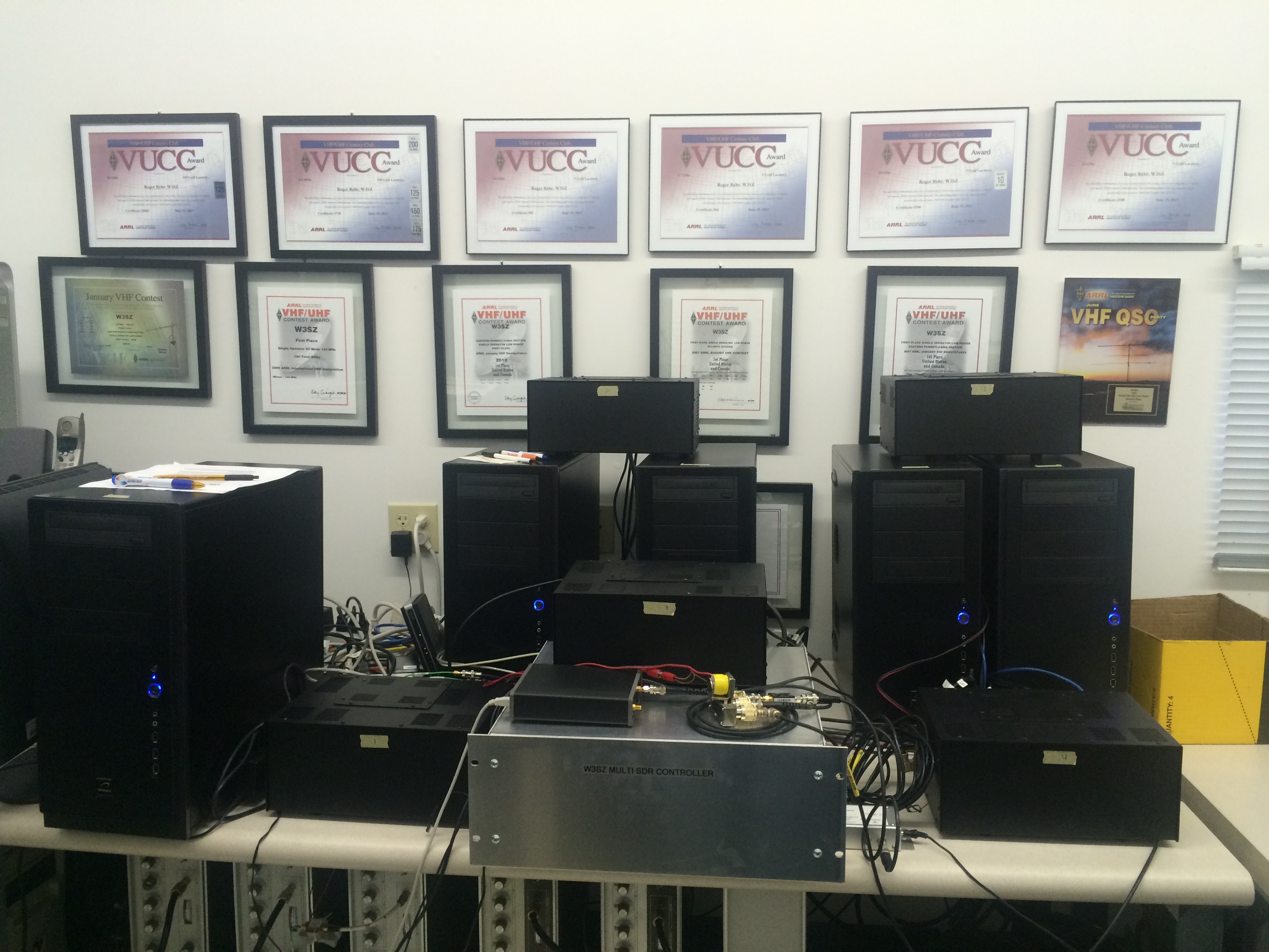
Below is a
picture of the now superfluous SDR controller and five of
the seven computers with their associated HPSDR units. The
sixth and seventh computers are off-screen.
This
software is not intended to be used without change by other
operators, as it was designed/built specifically to be used
at my station and has many features specific to my
circumstances, but the source code is provided with the hope
that it may help others in their software building efforts.
Below are links from which you can download the source code.
The size of the source code files will change as I tinker
with the software.
Client
~14 MB
Server ~26 MB
There is also a version that runs nicely using Mono on Linux, which is here. This file is ~122 MB and could be thinned down considerably.
The Windows code was compiled with Visual Studio 2013 --> 2022 and Framework
4.5 --> 4.8. The Linux code was compiled using MonoDevelop 7.8.4 (build2) and Framework 4.8. A few aspects
of the new coding are described below.
1. The
large FFT. A large FFT, used to reduce the bin size for the
spectrum display and waterfall, is essential for weak signal
work. I had previously added large bin sizes to the
openHPSDR version of PowerSDR and this was eventually
incorporated into the main open HPSDR PowerSDR trunk. I have
found that an FFT size of 262144 provides, for me, optimal
sensitivity. I included FFT sizes of up to 524288 in this
release.
The
optimal size of the FFT for audio processing and graphic
signal display are quite different. For this reason I kept
the audio FFT size unchanged in this software, and added FFT
size selection only to the graphical display code. The
architecture of the pre-existing software made using the
included SharpDSP FFT routines for this purpose difficult,
and so I first included a hand-coded FFT routine. This code
is contained in fourier.cs, which is included in source code
I distributed, but is not used. I ended up using FFTW.
This is written for C, but there is a nice wrapper for C#
use named FFTWSharp.
This did not include support for using Wisdom to optimize
the FFT calculations, so I made a simple extension to the
dll to permit Wisdom use. This extension merely consisted of
adding the following lines to the code:
/// <summary>
/// W3SZ imports a wisdom plan
/// </summary>
/// <param name="plan">The plan to
output</param>
[DllImport("libfftw3f-3.dll",
EntryPoint = "fftwf_import_wisdom_from_filename",
ExactSpelling = true,
CallingConvention = CallingConvention.Cdecl)]
public static extern int import_wisdom(string filename);
/// <summary>
/// W3SZ exports a wisdom plan
/// </summary>
/// <param name="plan">The plan to
output</param>
[DllImport("libfftw3f-3.dll",
EntryPoint = "fftwf_export_wisdom_to_filename",
ExactSpelling = true,
CallingConvention = CallingConvention.Cdecl)]
public static extern int export_wisdom(string filename);
}
The
modified DLL is included with my source code distribution,
and the FFTWSharp source as modified by me is available here.
If the modified DLL is included in the project bin directory
and appropriately referenced by the C# project, no
additional coding is necessary to use the extended DLL.
2. Audio.
Unlike PowerSDR, the original KISS Konsole did not provide a
computer audio stream so that the user could listen to the
HPSDR hardware using the computer audio
system/speakers/headphones. Instead, one needed to obtain
audio from the headphone jack of the HPSDR hardware
[Mercury/Hermes/etc.]. I added computer audio output, first
using the Naudio
C# wrapper for Windows audio functions. Naudio can be added
to C# using the Nuget
Package Manager, which integrates very nicely into Visual
Studio. Ultimately I decided that the CSCore
audio
package provided some advantages over Naudio, and so the
final code uses CSCore audio rather than Naudio. The code to
add audio to KISS Konsole was minimal, but it took me a bit
of trial and error to optimize it. Receive audio is
available at either the server computer, the client
computer, or both depending on user selection. As noted
above, the Opus codec is used to reduce both receive audio
and mic audio ethernet bandwidth requirements.
Since the
text above was written, I have added the ability for the
user to adjust some parameters of the Opus codec. I
did this to improve the performance of the radio when used
for the digital modes. Codec parameters of bitrate,
audio bandwidth, and codec type (Voip or Audio) can be
adjusted by the user, with separate states permitted for
voice and digital modes, and for receive and transmit.
Bitrate can be varied from 8192 through 131072 in
multiple steps and bandwidth can be varied from 4 kHz
through 20 kHz.
I have added frequency-domain frequency-specific AGC, because time-domain AGC is ill-suited to use with
the digital modes. Each FFT bin has its own AGC, so that strong signals within the passband do not
reduce the sensitivity for weaker signals as would be the case with time-domain AGC. There are two user adjustable
parameters for the FAGC: maximum amplitude ("limit") and "knee". No signal's amplitude can exceed "limit", and
signals at or below the "knee" amplitude are passed through the FAGC without amplitude change. The equation used for
amplitude reduction for signals above the knee is of the form:
output = limit * (1.0 - (Math.Exp(-w * input magnitude)) * input
where "input" is the complex input signal for a given FFT bin and "output" is the complex output signal.
3. CW
Sidetone. I also used CSCore to provide a CW sidetone. When
doing remote operations, having a sidetone generated by the
HPSDR hardware is unsatisfactory. So under those
circumstances, the sidetone generated by the WinKeyer is
used (or, alternatively, the sidetone generated by the
client software at the operator's location which has no discernible delay is used).
4.
Filters: I have added the ability to choose from
multiple filters: Welch, Rectangular, Hamming,
Riemann, Hann, Blackman 2, 3, or 4 tap, Blackman-Harris 4 or
7 tap, Parzen, Bartlett, Exponential, Dolph-Chebyshev, and
Kaiser. For the Dolph-Chebyshev filter ultimate
attenuation can be varied, and for the Kaiser filter Alpha
can be varied.
5.
Split Operation: I have added capability for
split operation, with the receiver using VFO A and the
transmitter using VFO B when split operation is selected.
6.
Digital Mode Compatibility: I have done several
things to optimize digital operation. One can select
custom codec parameters that are automatically used when
digital operation is selected. I have added additional
integral virtual serial ports so that the Main and Aux
radios can communicate both with N1MM and also with two
separate instances of WSJT-X simultaneously without
interference or conflict. The Main and the Aux Radio
can each run a separate instance of WSJT-X (or another
digital program) with each of these two radios having
separate CAT control, Rx audio, and Tx audio virtual
connections with its associated instance of WSJT-X.
7. Remote
Capability. The software allows operation of the system from
a remote location, using either wired or wireless ethernet
communications. A computer microphone is used for transmit
audio, a CW Key with or without WinKeyer is attached to a
COM port of the computer running the client software at the
operator's location and is used to generate CW, and a
footswitch is attached to the same COM port and is used to
provide convient MOX control, although the onscreen MOX
button can also be used. Full operation of the station from
50 MHz through 24 GHz with automatic bandswitching is
possible from a remote location. I use this software on a
daily basis to operate my remote station from home. Having
the ability to use my station remotely has greatly increased
my operating time.
8. The Linux version has a buffer modified from Jim Ahlstrom, N2ADR's code, that sits between the server and the SDR to smooth out any variability in the transmit data being sent from the server to the SDR. The code runs in a separate xcfe4 terminal window that starts when the server is started and shuts down when the server is shut down. Jim's site that describes the buffer and contains his source code is here.
If you
have any questions on the coding, or even better,
suggestions, please email me. If you hold an amateur radio
license, then you will know how to contact me in this
manner. Also, you can find an updated pdf file based on the
text of a talk I gave at the PackRats Mid-Atlantic VHF
conference on this project here
and a pdf file of the slides I used for that presentation here.
Copyright
1997-2024 COPYRIGHT Roger Rehr W3SZ. All Rights Reserved.
Brought
to you by the folks at W3SZ