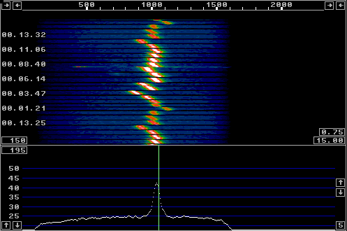
Fig 1.The file poltest_10_GHz_1.wav as seen on the Linrad S-meter. The recording is repeated endlessly, this is one option available in Linrad for this kind of evaluation purposes.
|
There have been endless discussions about whether it would
be worthwhile for the 10 GHz EME community to adopt circular
polarization as the official standard. To take a decision
one needs to know how large the depolarization is for a
linearly polarised wave.
The amount of depolarization depends on what parts of the moon are illuminated. With very big antennas it is possible to illuminate small areas on the moon and the depolarization may be very different from what one would observe with modest antennas of the size amateurs typically use for 10 GHz EME. On April 2 2006 some tests were made with signals emitted from the 20 m parabola at Bochum by the DL AMSAT group. These signals were received by OK1KIR among others. Look for details here: OK1KIR_pol.test.rtf Several data files were recorded and they can be found at http://www.qsl.net/ok1vao/10GHz_pol_test When using Linrad to evaluate the signal level it is possible to use a signal adapted filter. (A filter that has a shape that is similar to the power spectrum of the signal. Such a filter will provide the best possible S/N.) This is made possible by the Linrad AFC which keeps the signal accurately placed at the center of the filter. Figure 1 shows the recording poltest_10_GHz_1.wav as it looks when played as the input to Linrad-02.18. The file consists of 19 separate sequences recorded at polarization angles from -90 over 0 to +90 degrees in steps of 10 degrees. |

Fig 1.The file poltest_10_GHz_1.wav as seen on the Linrad S-meter. The recording is repeated endlessly, this is one option available in Linrad for this kind of evaluation purposes. |
|
The noise floor of the measurement is at 31.5 dB and the optimum
S/N is about 24 dB. When the receive polarization is orthogonal,
S/N is about 10 dB lower.
One can clearly see there is an inconsistency in the measurement
in that the level at -90 degrees is about 0.7 dB lower than than
the level at +90 degrees. These levels should have been equal.
(Maybe the lobe moved slightly for a slightly different reflection
coefficient?)
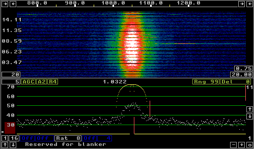
The well known result from the test with the Bochum radio telescope does not answer the question about depolarization with "normal" antennas that illuminate the entire moon. With the big antenna all the transmitted power is reflected back with whatever reflection coefficient the moon has at its center. With an antenna that illuminates all of the moon a substantial fraction of the power is lost into outer space and one can expect the signal levels to become much lower. With the measurement method presented here it should be possible to extract accurate information from measurements at much lower signal levels. The main spectrum and its associated waterfall graph is shown in figure 2 and the baseband spectrum with its associated waterfall graph is shown in figure 3. |

Fig 2.The file poltest_10_GHz_1.wav as seen in the Linrad main window. This image is cut from the same screen as figure 1. |

Fig 3.The file poltest_10_GHz_1.wav as seen in the Linrad baseband window. This image is cut from the same screen as figure 1. |
|
As can be seen from figure 2 it would have been necessary to
use a bandwidth of at least 400 Hz to evaluate the signal
level without an AFC.
The filter used for figure 1 is only 50Hz at the 3 dB points
as can be seen in figure 3 so the advantage in S/N is in the
order of 10 dB for the evaluation presented here over a
conventional RMS power measurement in a fixed bandwidth.
|

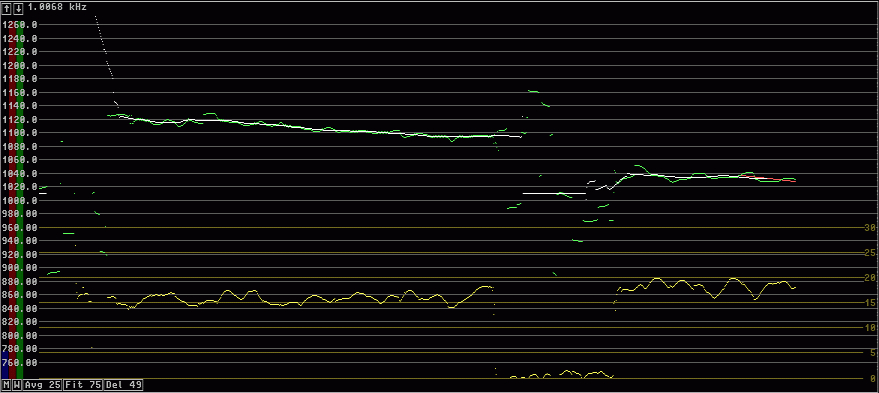
Fig 4.The file poltest_10_GHz_1.wav as seen in the Linrad afc window. This image is cut from the same screen as figure 1. Note that this image is downscaled to 75% of its original width. |
|
Figure 4 shows the afc window during the weakest period.
The yellow graph shows the S/N ratio within the AFC process,
it goes from about 16 dB during the weakest period to about
18 dB in the subsequent period.
The filter bandwidth is 21 Hz so 4 dB less noise is received
while about only 3 dB less signal is received.
The statistical uncertainty is not optimal however.
The Linrad AFC locks well down to S/N = 0 dB or (S+N)/N = 3dB for signals like those displayed on this page so it will not be difficult to evaluate measurements of signal level versus polarization offset when wav files from such measurements become available. The parameter files used with Linrad-02.18 are these ones: poltest poltest_ag poltest_bg poltest_cg poltest_mg poltest_wg The entire screen is shown in figure 5. |

Fig 5.The entire 1280x1024 screen from which the figures 1 to 4 were extracted. |
|
To SM 5 BSZ Main Page |