|
Linrad-01.05 and later versions have a tx test mode.
This is a mode that makes the evaluation of transmitters
easier.
Just connect the transmitter to test to the antenna input
of your hardware with appropriate attenuators in between.
Press the key on the main menu for Tx test mode and
watch the sceen. Press 'G' to save it as a gif file.
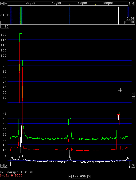
In tx test mode, Linrad shows three different spectra at the same time. The spectrum in white is the conventional spectrum always present in Linrad. It is the average power spectrum at the bandwidth specified by the fft1 parameters as usual. The spectrum in red is the average spectrum in a flat bandwidth of 2.4 kHz. The red spectrum shows what one would experience when using a normal transceiver in SSB bandwidth. The green spectrum is the peak power spectrum in SSB bandwidth. It shows the maximum peak amplitude that has occurred since the latest reset. (Press Z for reset) The peak spectrum will show splatter peaks and all kinds of emissions that may be taking place at irregular intervals. It is like the peak hold function on any spectrum analyzer. Figure 1 shows a pure crystal oscillator. This is a demonstration of filter responses, spurs and dynamic range. The hardware is WSE RX144 -> RX70 -> RX10700 -> RX2500 -> Delta44. The red curve shows a dynamic range of about 111 dB. This corresponds to 145dBc/Hc when the 2.4 kHz bandwidth is taken into account. The signal is at about 144.012 MHz, the spur at 144.088 is the mirror image spur. This is a typical level for a calibrated system, just a little bit better than 70 dB. The spur at 144.048 is the zero frequency noise. In a direct conversion receiver, the center of the passband is at frequency = zero and there 1/f noise degrades performance. The peak to average ratio is a bit larger on this spur compared to the 10 dB that is typical for white noise. Note that the peak to average ratio is 0dB for a pure carrier.
|
|
Fig 1.
A pure crystal oscillator.
This screen dump shows spurs and the noise floor.
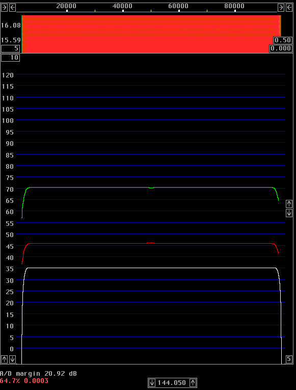
Figure 2 shows pulses at low repetition rate. These pulses have a flat spectrum as can be seen very clearly. The peak to average power is 25dB, much higher compared to white noise which is typically 10 dB as can be seen in fig. 1.
|
|
Fig 2.
Pulses at prf = 100 Hz.
This screen dump shows the amplitude vs frequency response.
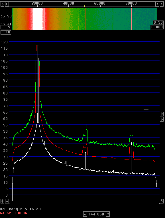
Figure 3 shows an IC-706MKIIG emitting a constant carrier. The phase noise is at -117dBc/Hz at a separation of 20 kHz. The spurs are small and there are no spurious emissions at the sides of the signal, the peak power is 10 dB or less above the average power.
|
|
Fig 3.
An IC-706MKIIG emitting a pure carrier.
The average power (red) is at -83dB at a frequency separation
of 20 kHz in 2.4 kHz.
This converts to -117 dBc/Hz.
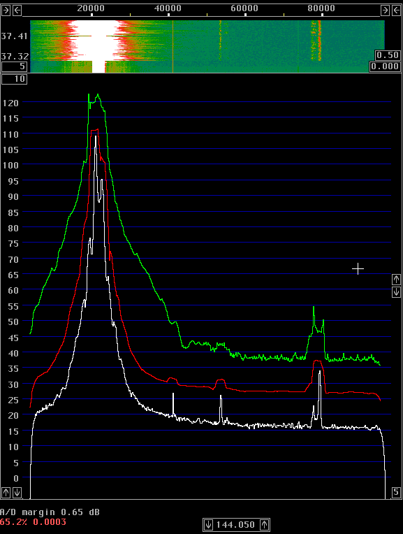
Fig. 4 shows the spectrum of the same IC-706MKIIG when hand keyed. The keying clicks are strong at a separation of about 5 kHz, but at 15 kHz the keying clicks have disappeared into the noise floor.
|

|
Fig 4.
An IC-706MKIIG when keyed at normal hand keying speed.
Keying clicks can be seen as peak powers more than 10 dB
above the average power.
Fig 5 shows the spectrum in SSB mode. The splatter goes into the noise floor at about 20 kHz frequency separation. With a "DX voice" into the microphone, the peak to average power is about 10dB. At a frequency separation of 10 kHz, the peak power of the splatter is about 20 dB above the peak power of the noise floor. This is 50 dB below the peak power of the signal itself.
|
|
Fig 5.
An IC-706MKIIG in SSB mode.
The peak hold spectrum in green shows worst case interference
while I have tried to be as nasty as possible with the microphone.
|