Theory of operationLinrad has a number of digital PLL's (phase locked loops) that can be locked to phase stable signals that are present in the input spectrum.The general theory about PLL's is described by many others and there is no reason to go deeply into it here. Basically a digital LO (local oscillator) is set up with the same frequency as the offending spur. The LO is used in two mixers to produce I and Q (quadrature mixing) and Q is used to control the phase/frequency of the LO through an appropriate loop filter. The LO of the PLL has ideally the same phase as the spur. The spur amplitude is the I signal. In the presence of noise there will be errors in the LO phase and the I signal, but by selecting a narrow loop filter and filtering I through a similar filter the noise can be suppressed. Once the amplitude and phase of the spur is known a signal with the same amplitude and opposite phase can be generated and added to the wideband signal before it is further processed. This way the spur is cancelled without any effect on desired signals at the same frequency, provided that the desired signals have much larger bandwidth than the bandwidth of the loop filter.
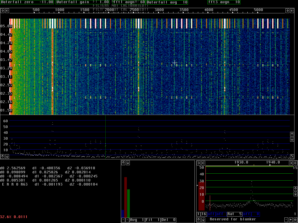
Many PLL's can run at the same timeThe digital PLL's used for spur cancellation use the same fft's that are used for the waterfall graph. The time constant of the loop filter corresponds to a number of transforms. Both the mixers and the filters are obtained by combining the complex amplitudes from the appropriate number of transforms and the spur is cancelled in the frequency domain. This way the CPU load is pretty small and hundreds of spur PLL's may be running simultaneously.Figure 1 shows the screen when an audio generator with a complex waveform was connected to the audio board. There are about 70 PLL's running for most of the time of the waterfall graph. The PLL's are switched off at about 05.00 causing the top of the waterfall and the main spectrum to show the spurs at their true level. The audio generator is not particularly phase stable so the PLL's can not have a very narrow bandwidth. Only spurs that have a good S/N at the bandwidth given by the loop filter can be removed. Note that very weak spurs are treated with much less efficiency than stronger ones. Spurs that are more than 40dB above the noise are not treated with high enough accuracy with the current combination of parameters. The PLL's only takes 7 fft bins into account and very strong spurs need more.
|
In real life it is harder. Spurs often drift slowly in frequency and they may have a random phase modulation as well as varying amplitudes.
A conventional loop filter that would allow a reasonable frequency drift would have to have a rather large bandwidth and would therefore not allow locking to weak spurs since their S/N would not be good enough at such large bandwidths.
The loop filter for the spur PLL's in Linrad contains an AFC. The transforms corresponding to the loop filter time constant are combined in the way that gives the best fit to a signal with constant frequency drift.
To avoid processing delay the PLL loop filters use old transforms plus the latest one so the strategy is less good than it would be if the fit was done with data that extended for an equal amount of time in both directions. The AFC opens the bandwidth, it allows some extra noise to enter the LO phase and the cancellation signal amplitude. When the noise causes large enough phase errors, locking is no longer possible.
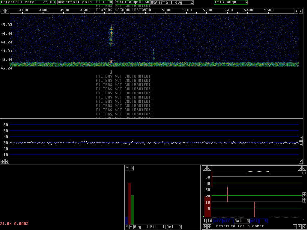
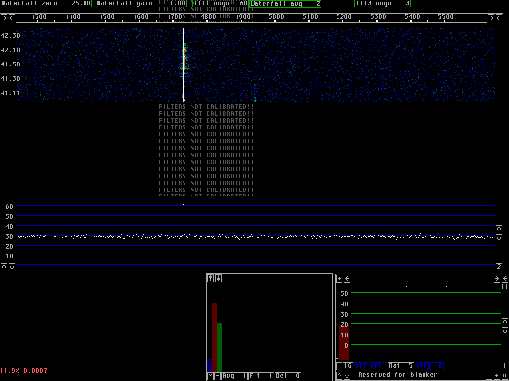
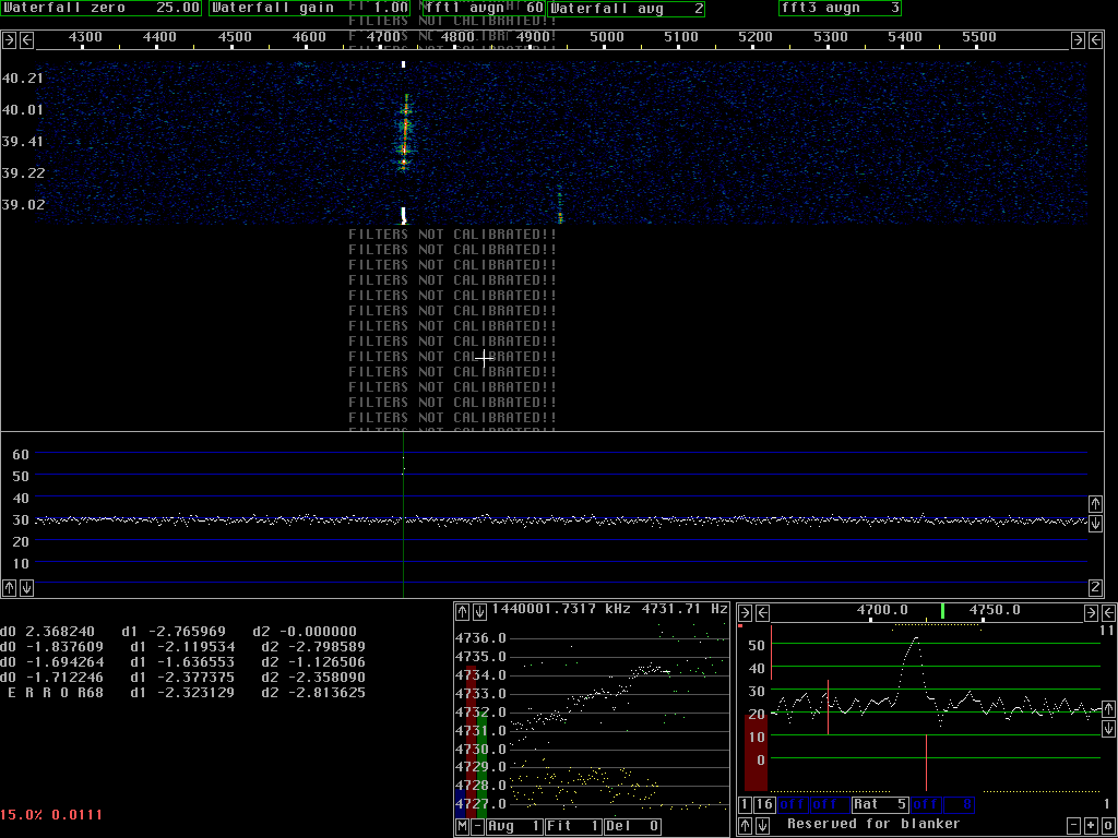
Fig. 2 shows two PLL's running at the limits of unlock conditions. One spur is frequency modulated while another spur is very weak.
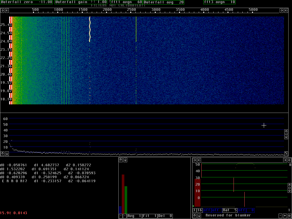
Fig. 4 shows the same sequence of the recording as fig. 3 but a spur is added by means of an audio generator. The combined signal was recorded on the hard disk to allow Linrad to process exactly the same input with and without spur cancellation.
Fig. 5 shows how the PLL removes the spur completely. Note that figures 3 to 5 are zoomed in and only cover 1.3kHz. An expensive window, sin to 4th power was selected to make the spur narrow and this way allow the keying sidebands to be seen in fig.4.
In a normal use of Linrad with 30 to 94kHz bandwidth in the waterfall graph, the data behind the waterfall graph would be the same but with 30 to 100 data points for each pixel the EME signal would have been completely invisible without the spur PLL. Note that the spur PLL removes the spur completely. This spur has good phase stability and the PLL time constant is 3 seconds.
