1. Smoke test
Connect the coaxial cables from the output of the RX144 unit to the RX70 unit and make sure that the RX70 is connected to the RX10700 which in turn should be connected to the RX2500, the computer and to the power supply. Do not connect the d-sub connectors to the RX144, RX70 or RX10700 units unless you are sure the boxes are properly connected to the computer chassis and the power supply zero. The parallel port interface is an open drain, a 74HC03, and it may be damaged by static electricity. Making sure that ground is connected before the cable to a computer parallel port is connected is always a good idea. Replacing the 74HC03 which is mounted in a socket is trivial, but if the computer parallel port is damaged, repair is not easy.Connect the 9-pin d-sub connectors to the RX144, RX70 and RX10700 units to supply DC voltages and connection to the computer parallel port. Look here for details: Controlling WSE units from within Linrad
In case the current differs much from the nominal 0.7 A something is wrong. There is not yet any experience on faulty boards so I can not give detailed hints for troubleshooting.
2. Tune the crystal oscillator
If the board is new and has not been tuned before, set C5, C7, C15 and C27 for maximum capacitance. Start Linrad and enter the weak signal CW mode by pressing A. In case Linrad was already running, you have to exit and re-enter by pressing X, then B. This way you clock data into the 74HC174 flip-flops and send current to one of the oscillator transistors. Set the frequency in the Linrad frequency control window to 144.5 MHz. The voltage on R5 (and C2) should now be -4.5 V.Monitor the voltage on the emitters of Q5 and Q6 by connecting a voltmeter to R20. R20 is located next to R22 but due to space limitations the component text is right under the resistor. When the LO is not oscillating, the voltage is about -0.75 V with respect to ground. Tune C41. When oscillations start, the voltage will go slightly more positive. Set C41 for maximum at typically -0.65 V. Note that there are two maxima; the crystals have their fundamental frequency at about 25 MHz and may oscillate around 125 MHz if C41 is set close to minimum capacitance. When correctly tuned, C41 is at about 60%.
Set C82 and C95 for about 30% capacitance. Then monitor the Q7 and Q8 source voltage on R31, while tuning C40 for minimum. Q7 in parallel with Q8 is a buffer amplifier. When the drains come into resonance the transistor will saturate and the current decrease. Tune C85 for maximum on J6 and C92 for maximum on J7. The J6 and J7 voltages are negative and should be around -4V. The LO buffer amplifiers will be fine tuned at a later stage but you may already at this point adjust C82 together with C85 or C95 together with C92 if the J6 and J7 voltages differ by more than 1 volt.
When the LO mixer buffers Q38 to Q45 are tuned, the LO buffer Q7 and Q8 will be properly loaded. The mixer buffers use noiseless feedback and the load they present to L14/C40 is strongly dependant on tuning. Retune C40 while monitoring the source voltage at R31. This time the minimum should be sharper and deeper.
The crystal frequencies are 74.0, 74.5, 75.0 and 75.5 MHz. In case you are coarse tuning the board outside its box, you may use a frequency counter to set the frequencies about 250 Hz above the nominal frequencies. While tuning each frequency with
The temperature coefficients of the crystals is not equal. Tuning cold for a frequency error of 250Hz will typically lead to frequency errors within +/- 250 Hz for the warm unit.
3. Coarse tune filters
Tune one channel at a time. Use a signal somewhere in the middle of the 144 MHz band and measure the signal level at the 70 MHz output. One way of doing it is to use Linrad in tx test mode with the RX70, the RX10700 and the RX2500 converters, but any spectrum analyzer or receiver that can be used at 70 MHz will be fine. A suitable signal level is -25 dBm. When the RX144 unit is properly tuned the conversion gain is about 8 dB but before any tuning is done the conversion gain is in the order of -50 dB. The local oscillator is only about 4 MHz above the converted 144 MHz signal and it is much stronger so tuning can neither be done with a diode detector nor with a network analyzer in frequency conversion mode.When the tuning capacitors arrive from the factory they are set for maximum capacitance. Before tuning the filters, set C57 and C89 for minimum capacitance. These two capacitors set a notch at 152 MHz and during the coarse tuning the notch should be left far above 144 MHz. Before coarse tuning, also set the coupling capacitors C66, C68, C100 and C106 for about 2 pF, that corresponds to about 1 mm overlap of the metals at the periphery.
Tune the capacitors of channel 1 for maximum in the following order: C98, C104, C107, C110, C97, C122, C117, C116, C122, C117, C97, C107. Note that a few capacitors are tuned twice. All capacitors affect each other to some extent but tuning in this order should be accurate enough to give a good starting point for the fine tuning procedure.
For channel 2, the recommended tuning order is: C65, C67, C71, C74, C63,C79, C58, C60, C79, C58, C63, C71.
The coarse tuning gives the unit a conversion gain of 7 +/-1 dB at the test signal frequency.
4. Coarse tune the 152 MHz notch filters
The LO at 74 MHz will generate a third harmonic at 222 MHz internally in the mixer. Having 222 MHz in the mixer will create spurious responses at 152 and 292 MHz. The response at 152 MHz is close enough to 144 MHz to be a potential problem, therefore a notch is incorporated in the RF filter. The notch improves the spur suppression from about 50 dB to about 70 dB. To tune the notch, just change the frequency from the coarse tuning frequency to the spur frequency and tune for minimum. C89 for channel 1 and C57 for channel 2. If Linrad is set to 144.3 the spur signal should be a few kHz from 151.7 MHz. It may be convenient to combine a signal near 144.3 with a signal at 151.7 in case several RX144 units are to be tuned.5. Balance the mixers and fine tune LO drive
The LO power is in the order of +25 dBm at the mixer input and the LO frequency 74.0, 74.5,... is close to the IF frequency range 70 to 70.5 MHz. The noise floor at the output of the mixer is at -172 dBm/Hz (NF=2dB) so in order to not degrade performance, the sideband noise of the LO that leaks through the mixer should be below -182 dBm/Hz. Without balancing, the mixer could suppress the LO leakage by as little as 20 dB which would call for an LO with a sideband noise level of -187 dBm/Hz. The RX144 LO is good, but not quite that good and therefore a capacitor and a resistor is used to tune the mixer balance.The capacitances of the J310 transistors depend on the DC bias which in turn is determined by the LO drive level so balancing depends on the LO tuning and which crystal is selected. With the capacitor set for max capacitance and with the potentiometer in its middle position, the level of the LO signal is typically +5 to +15 dBm.
Use Linrad in "ANALOG HARDWARE TUNE" mode and select RX144. This will make the the unit switch between the crystals and use all of them. For channel 1 the balancing is adjusted by C103 and VR2 while channel 2 is balanced by C77 and VR1. Alternate a few times between the capacitor and the potentiometer but start with the capacitor. The level of the LO fundamental should be below -15 dBm for all crystals.
Use some kind of level detector at the IF output. A schottky diode will work fine but it will not show the actual level of the leakage unless a filter is added to remove the overtones of the LO which are at about -20 dBm. Best is to use a 100MHz low pass filter and an oscilloscope. Trigger the oscilloscope on XTAL_1, pin 14 of U6 or R4 ans adjust the sweep time so you can see tha balance of all four crystals.
With the oscilloscope still triggered on XTAL_1, monitor the voltages on J6 and J7. This voltage should be the same for all four crystals. J6 and J7 have two pins each. Monitor the one with the smallest voltage. The LO buffer amplifier uses noiseless feedback which means that the input impedance vill change when the load impedance changes. Consequently the two buffer amplifiers affect each other because the load on the common drive signal will be the simultaneous load from both LO buffers. The summed load from both of the LO buffers will affect the tuning of C40. All five capacitors C40, C82, C85, C95 and C92 affect each other. To get rapid convergence, first tune C85 and C92 simultaneously for both test points to give a voltage that is flat, i.e. a voltage that is the same for all crystals. Then tune C40 for the first and the last crystal to both be close to maximum simultaneously. Then tune C95 and C92 simultaneously to shift the channel 1 voltage or C82 and C85 simultaneously to shift the channel 2 voltage. The voltages on J6 and J7 should be between 4 and 5 volts. Finally check the LO leakage into the IF output and adjust the balance if necessary.
Fine tune the RF and IF filters
The fine tuning procedure uses a pulse generator. Set the pulse repetition frequency somewhere in the range 200 to 2000 Hz. Select a repetition frequency that gives a steady reading on the Linrad screen.To have the pulses injected into both channels simultaneously, use a hybrid followed by two 10 dB attenuators. The hybrid will isolate one input from the other only if the output impedance of the pulse generator is 50 ohms. Without the attenuators, the tuning of one channel will affect the other channel if the pulse generator is a parallelled 74AC74 or similar. The filter tuning has some influence on the input impedance.
Connect the RX144, RX70, RX10700, RX2500 and the computer as described above and enter the J=ANALOG HARDWARE TUNE mode. Then select RX144. With a correctly tuned RX144 unit you should see two spectra side by side as shown in fig. 1.
Fig.1. The screen in ANALOG HARDWARE TUNE mode. The distance between the horizontal lines is 1 dB. The spectra can be moved up or down with the '+' and the '-' keys. This unit is correctly tuned.
The ANALOG HARDWARE TUNE mode measures one 90kHz wide spectrum for each crystal. The center frequency is 70.2 MHz at the IF so these spectra show 144.155 to 144.245, 144.655 to 144.745, 145.155 to 145.245 and 145.655 to 145.745 MHz.
Another way to tune the RX70 RF filters is to use a network analyzer in conversion loss mode. Then tune for a flat response from 69.9 to 70.5 MHz. In this case it does not make much difference which crystal has been selected, a few tenths of a dB only, but since one crystal has to be selected it seems natural to select the 74.5 MHz one by selecting 144.5 MHz in the Linrad window.
The 144 MHz RF filter uses several LC circuits. The tuning points do interact and tuning capacitors one by one at random may give a slow convergency. Here is a way that gives rapid convergency:
1a) Tune C98 for maximum. This is to restore resonance caused by the interaction from the notch. In case coarse tuning and notch tuning were done with two signals, one near 144.3 and one near 151.7 MHz C98 should already be tuned for maximum and you could start at the next point.
2a) Tune C107 for the flattest possible response under the constraint that the maximum value is no more than 0.5 dB below the largest possible value.
3a) Tune C98 and C104 simultaneously. These trimmers interact somewhat. Set C98 at different positions and tune C104 or vice versa. Look for the optimum combination giving a high and flat curve.
4a) Retune C107.
5a) Adjust C100 for the capacitance that gives 0.25 dB less than maximum gain. The capacitance has to be smaller than that giving maximum gain. Then adjust C105 the same way.
6a) Tune C97, C110, C116, C117 and C122 for maximum amplitude and flatness. The capacitors do not interact much now when tuning is nearly correct so the order is unimportant.
7a) Fine tune C98, C107 and C104. They should all be close to optimum but if one is changed, check the other two. The Linrad screen should be similar to figure 1 for channel 1 by now. If not, repeat the procedure for channel 1 from the second step.
1b) Tune C65 for maximum. This is to restore resonance caused by the interaction from the notch. In case coarse tuning and notch tuning were done with two signals, one near 144.3 and one near 151.7 MHz C98 should already be tuned for maximum and you could start at the next point.
2b) Tune C71 for the flattest possible response under the constraint that the maximum value is no more than 0.5 dB below the largest possible value.
3b) Tune C65 and C67 simultaneously. These trimmers interact somewhat. Set C65 at different positions and tune C67 or vice versa. Look for the optimum combination giving a high and flat curve.
4b) Retune C71.
5b) Adjust C66 for the capacitance that gives 0.25 dB less than maximum gain. The capacitance has to be smaller than that giving maximum gain. Then adjust C68 the same way.
6b) Tune C58, C60, C63, C74 and C79 for maximum amplitude and flatness. The capacitors do not interact much now when tuning is nearly correct so the order is unimportant.
7b) Fine tune C65, C67 and C71. They should all be close to optimum but if one is changed, check the other two. The Linrad screen should be similar to figure 1 by now. If not, repeat the procedure for channel 2 from the second step.
If the channels differ in gain, squeeze L17 and L35 so the gain becomes equal between the channels. Tighter coil = more inductance gives lower gain. Then tune C122 for more capacitance until the gain is lower by 0.5 dB in channel 1. Readjust C177. C122 should have more capacitance until the point where the gain with C117 on maximum is 0.5 dB lower than the gain with both capacitors tuned for maximum gain. Then tune C79 and C58 the same way for 0.5 dB less gain in channel 2. Giving the drain of the IF amplifier a reactive (capacitive) load impedance leads to a substantial improvement in intermodulation performance.
Checking gain and the point of 1-dB saturation.
The first 25 units were tested with a network analyzer in conversion gain mode to verify that the tuning procedure described above gives an acceptable result. The units were tuned with a pulse generator and Linrad in hardware tune mode even though tuning on a network analyzer is easier and faster. This was done to verify that it is possible to tune the WSE converters without the use of expensive test equipment.The gain was measured at 144.1 MHz at a power level of 3 dBm. The power was then turned up until the gain was 1 dB smaller. The result is listed in table 1.
Unit       Channel 1          Channel 2
        G(dB)  1dBsat(dBm)   G(dB)  1dBsat(dBm)
  1      8.6     9.6          7.7      10.6
  2      7.9    10.4          8.1      10.1
  3      8.1    10.2          8.1      10.3
  4      8.4     9.9          8.3      10.1
  5      7.8    10.5          8.0      10.4
  6      7.9    10.4          8.2      10.2
  7      8.3    10.0          8.1      10.3
  8      8.0    10.2          8.2      10.3
  9      8.1    10.2          7.8      10.9
 10      8.3    10.1          8.4       9.6
 11      8.2    10.3          8.1      10.3
 12      8.0    10.3          7.5      10.6
 13      8.2    10.1          8.0      10.4
 14      8.4     9.9          8.5      10.1
 15      8.1    10.1          8.0      10.6
 16      8.2    10.4          8.0      10.7
 17      8.4    10.0          8.2      10.4
 18      7.8    10.5          7.8      10.6
 19      7.9    10.5          7.8      10.3
 20      8.3    10.3          8.1      10.3
 21      8.2    10.2          8.3      10.2
 22      8.2    10.1          8.2      10.2
 23      8.1    10.3          8.1      10.4
 24      7.8    10.6          7.7      10.5
 25      8.0    10.3          7.9      10.5
Table 1 Conversion gains and 1-dB compression points
for the first 25 RX144 units.
Table 1 shows that the gain of the RX144 unit is 8.0 dB plus/minus 0.5 dB. The 1-dB compression point is about 10 dBm at the inputso the point of 1 dB compression at the output is +18 dBm which fits well to the input of the RX70 unit.
Checking third order intermodulation.
The RX144 unit produces intermodulation of similar magnitude in several stages. The total amount of intermodulation is therefore sensitive to the tuning, the balance between filter loss and IF amplifier gain. The tuning procedure desribed above does not optimize IM3, it varies over a range of 20 dB between the units.The first 25 units were tested with two signals at a power level of 0 dBm at 144.085 and 144.095 MHz. Table 2 shows the level of the third order intermodulation product at 144.105 MHz (IM3 at 144.075 is very similar).
Unit       Channel 1    Channel 2
            IM3(dB)      IM3(dB)
  1          -59          -62
  2          -47          -42
  3          -48          -55
  4          -47          -51
  5          -45          -62
  6          -50          -47
  7          -48          -44
  8          -46          -54
  9          -47          -53
 10          -48          -47
 11          -53          -49
 12          -52          -54
 13          -53          -54
 14          -46          -54
 15          -51          -48
 24          -52          -48
 25          -55          -50
Table 2 Level of third order intermodulation
for the first 25 RX144 units.
The input is two signals at a power level of 0 dBm.
IP3 ranges from +21 to + 31 dBm based on these numbers.
The output IP3 of the RX144 units tuned with the simple tuning scheme described above gives an output IP3 that is larger than the input IP3 of the RX70 unit which is at about +28 dBm. A more complicated tuning procedure that would ensure correct loading of all amplifier stages would improve IP3 by several dB, but system performance will not improve much in the RX144, RX70 combination so I do not tune more carefully than this.
Checking the noise floor
Under normal operation the noise figure at the input of the RX70 unit is in the order of 15 dB. To get a good visibility for the noise generated by the RX144 a wideband amplifier with a BFR91A was inserted in front of the RX10700 to give a noise figure of 9.5 dB at the input of the RX70 unit when testing the first 25 RX144 units. The reason that the amplifier was not inserted in front of the RX70 unit is that the leakage of the LO and all the LO overtones at the IF output of the RX144 unit would saturate the wideband amplifier. The noise floor of the RX144 unit is high enough to be well visible with a noise figure of 9.5 dB.Table 3 shows how much the noise floor increases when the output of the 25 first RX144 units are connected to an amplifier with a system noise figure of 9.5 dB.
Unit         Channel 1                Channel 2
        N(dB)  G(dB) N-G+8(dB)   N(dB)  G(dB) N-G+8(dB)
  1      5.8    8.6    5.2        6.3    7.7    6.6
  2      5.4    7.9    5.5        6.2    8.1    6.1
  3      5.3    8.1    5.2        6.3    8.1    6.2
  4      6.0    8.4    5.6        6.9    8.3    6.6
  5      5.2    7.8    5.4        6.7    8.0    6.7
  6      5.7    7.9    5.8        6.4    8.2    6.2
  7      5.7    8.3    5.4        6.6    8.1    6.5
  8      6.2    8.0    6.2        7.0    8.2    6.8
  9      5.6    8.1    5.5        6.9    7.8    7.1
 10      6.1    8.3    5.8        6.6    8.4    6.7
 11      6.1    8.2    5.9        6.0    8.1    5.9
 12      5.3    8.0    5.3        7.2    7.5    7.7
 13      6.0    8.2    5.8        7.1    8.0    7.1
 14      5.5    8.4    5.1        7.0    8.5    6.5
 15      5.3    8.1    5.2        6.2    8.0    6.2
 16      6.5    8.2    6.3        6.9    8.0    6.9
 17      5.9    8.4    5.5        6.3    8.2    6.1
 18      5.5    7.8    5.7        5.9    7.8    6.1
 19      5.9    7.9    6.0        5.5    7.8    5.7
 20      6.0    8.3    5.7        6.0    8.1    5.9
 21      5.8    8.2    5.6        6.4    8.3    6.1
 22      5.8    8.2    5.6        6.3    8.2    6.1
 23      5.6    8.1    5.5        6.6    8.1    6.5
 24      5.2    7.8    5.4        5.8    7.7    6.1
 25      5.9    8.0    5.9        5.9    7.9    6.0
Table 3N is the noise level at the output connector of
the RX144 measured by comparision with a 50 ohm dummy
load. The test system noise figure is 9.5 dB.
G is the gain taken from table 1.
As can be seen from table 3, the noise floor of the RX144 is typically 6 dB above the noise floor of the measurement system when the variation in gain is accounted for. Just adding the deviation from the nominal gain is not quite correct but since the noise from the RX144 is about 6dB (four times in power) larger the error is small enough. When the RX144 is used in front of a receiver with 9.5 dB noise figure, signals grow by 8 dB while the noise grows by about 6 dB which means that the noise figure of the system is 7.5 dB. The noise figure of the RX144 unit itself is typically 6.5 dB.
Checking close range reciprocal mixing and noise modulation
For this test a low noise crystal oscillator is needed.Run the Delta 44 in its lowest sensitivity mode ("+4dB" with ossmix). Inject a test signal at 144.05 MHz, 1 dB below saturation into the channels one by one. The noise floor at a frequency separation of 5 kHz should not increase by more than 1.5dB in a single channel.
The test signal, about 1 dB below saturation with a power level of -21 dBm is at 126.6 dB on the Linrad S-meter. The noise floor with a dummy load at the RX10700 input is at 13.1 dB in 1 kHz bandwidth which means that the system noise figure is 9.5 dB. At a distance of 5 kHz from the test signal, the noise floor is typically at 14.1 dB which corresponds to -142.5 dBc/Hz. At the point of saturation, the noise floor is below -143.5 dBc/Hz. Only a small fraction of this noise is due to reciprocal mixing from the RX144 local oscillator.
In the first production batch of 25 units, several boards failed this test. The failing units had a noise floors that was intermittently as high as 25 dB. These problems were traced to the quality of the soldering of the thin enameled wires of the ferrite cores. Heating the solder points for 5 seconds cured the problem in each case. (all units were subsequently resoldered, see below)
Checking wide range reciprocal mixing and noise modulation
Inject a test signal at 144.040 MHz with a level of +0 dBm into the channels one by one via a notch filter at 144.150 MHz. Set Linrad to 144.175 MHz so the strong signal will reach the RX2500 at 2.385 MHz, well outside the 2.5 MHz RF filter. Measure the noise floor at 144.150 MHz with and without the test signal. Run the Delta 44 in low gain mode ("+4dB"). The noise floor should not increase by more than 2.5 dB.This test gives the noise floor at 110 kHz separation for signals outside the visible passband.
Note that the sideband noise tests give an upper limit for the performance of the RX144 unit. What is measured is the entire receiver chain: RX144 -> RX70 -> RX10700 -> RX2500 -> Delta44 -> Linrad. At a frequency separation of 5 kHz, reciprocal mixing and noise modulation contains contributions from all six processing blocks. At 110 kHz separation, the Delta44 is protected by the filters inside the RX2500 unit, but still the sideband noise is the sum of the contributions from four units.
Without the test signal the noise floor is at -164.5 dBm/Hz because the noise figure is 9.5 dB (see above). If the noise floor increases by 2.5 dB, the noise due to reciprocal mixing is at -165.5 dBm/Hz which means that this test ensures that the reciprocal mixing noise floor is at 165.5 dBc/Hz or below.
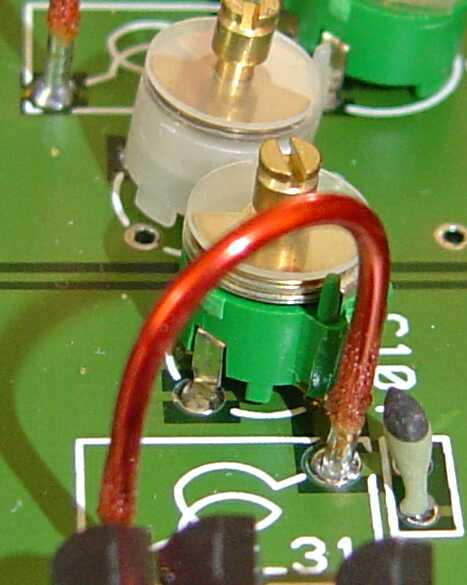
In the first production batch of 25 units, most boards failed this test. The typical "reciprocal mixing" noise floor was -162 dBm/Hz. These problems were traced to the quality of the solderings. The RX144 contains many trimmer capacitors and the supplier (BC Components, formerly Philips) advices us to not wash these trimmers with water. Therefore these trimmers are always hand soldered. Since the number of trimmers is so large, everything on the RX144 was hand soldered. The problem with hand soldering resonant circuits at high frequencies is that it is not enough to have the tin float well on the solder side. The tin must float well on the component side also, else the contact point to the component wires becomes uncertain and noisy. Figure 1 is one example where a coil is soldered well on the solder side but where the tin has not wetted the wire properly on the component side.