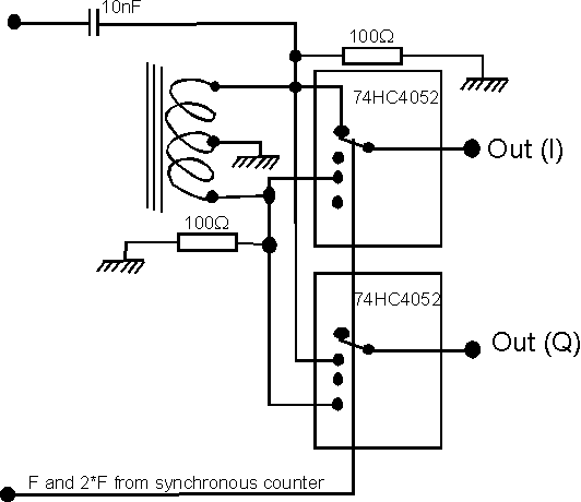
I/Q mixer for direct conversion radioA direct conversion radio needs a very good mixer. A strong signal near the passband center will produce strong audio signals at low frequencies (i.e. 1kHz). The mixer has to have a very low second order intermodulation to avoid a spur at twice the frequency,(2 kHz).If the second order spur is allowed at -40dB below the strong undesired signal a standard schottky mixer (7dBm LO) may be fed with about -13dBm. The output with a 50 ohm load is then about -20dBm. If this output level is amplified to near saturation of a Delta44 A/D converter, the noise floor at the amplifier input has to be at -125dBm in SSB bandwidth to only degrade performance by 3dB. I do not know how to make a DC to 100kHz amplifier with a noise figure below 10dB for a 50 ohm source impedance, but that is what is required - and then the second order spur will be only 40dB below the interfering signal. The simple HCMOS mixer in fig 1. produces a second order spur at -50dB when the level is adjusted for a standard low noise op-amp to degrade the dynamic range by less than 3dB. I have used Fairchild RC 4136 which is specified 10nV/sqrt(Hz). The -50dB second order spur is produced with an input signal level of +3dBm. The output voltage is 90% of the input voltage if the load impedance is 1 kiloohm. (The output impedance is about 300 ohms) This mixer is by far superior to a standard schottky mixer and it is probably about 20dB better than a high level schottky mixer.
|

