|
Comment added Sept 3 2002 This is an old page showing measurements with a tone generator on a Delta 44 that still has its input amplifier/filter in place. It is left here because it shows how such measurements can be done.
Two tone dynamic rangeThe two tone dynamic range is the ratio between the strongest signal that can be tolerated and the noise floor. The two tone dynamic range is usually limited by noise sidebands in transmitters and receivers. Look here for Some data on 1970 style transceiversThe two tone dynamic range is the same as the distance to the noise floor for the strongest signal that can be tolerated. The noise floor depends on the bandwidth, in the old days the noise floor was often measured in SSB bandwidth (2.5kHz or so) while modern measurements usually give noise floors in dB/Hz. Typical two tone dynamic range at 25kHz frequency separation is 90 to 100dB for a good, 25 years old 144MHz transverter. This corresponds to 124 to 134dB/Hz. Modern equipment seems no better according to noise sideband measurements in QST.
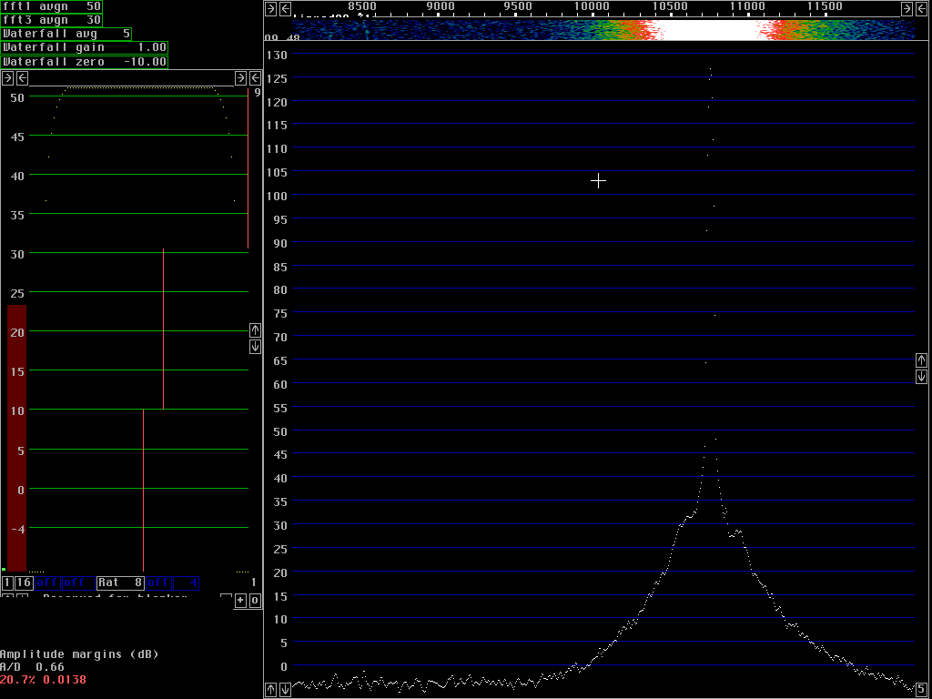
Test equipmentThe level an unwanted signal can have before causing a 3dB S/N loss on the desired signal is limited by A/D converter saturation when the receiver is a Delta44 A/D converter. There are some particular frequencies where the dynamic range is much lower compared to the rest of the spectrum and that is the overtone frequencies.The linearity of the A/D converter is better expressed as the level of the overtones than as dynamic range numbers. To be able to measure the level of the overtones created by the A/D converter it is necessary to have a signal with extremely low overtones. I have used a conventional audio oscillator, an OLTRONIX RCO-6 which gives a spectrum as shown in fig. 1.
|
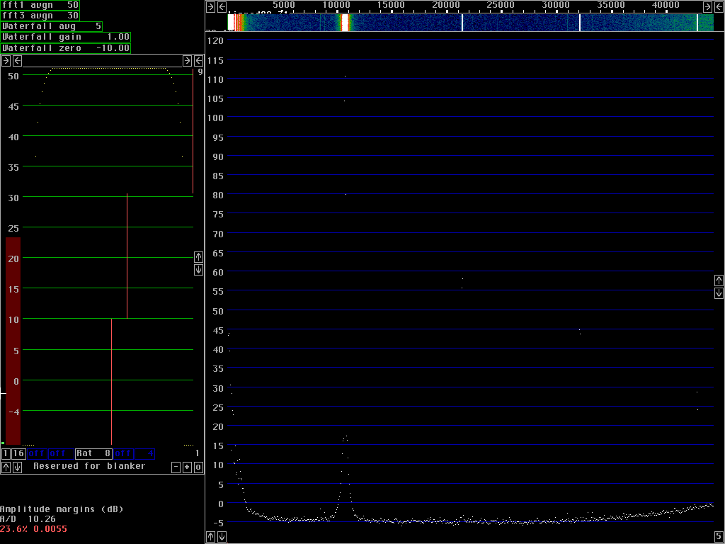
By combining the overtone content data of the audio generator from fig. 1 with the filter characteristics obtained from fig. 2 and fig. 3, the following overtone contents of the filtered test signal are obtained.
Fundamental 0dB
2nd harmonic -123dB
3rd harmonic -156dB
4th harmonic -172dB
The overtone levels obtained this way may be far too low, it is possible that overtones are generated in passive components for example.
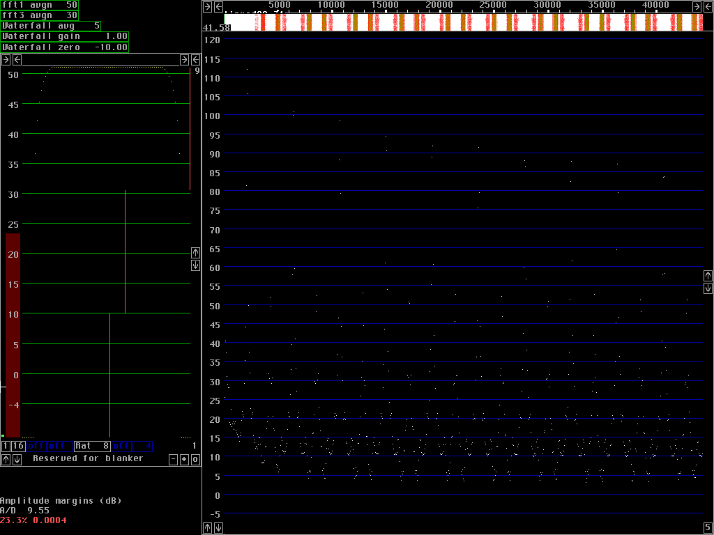
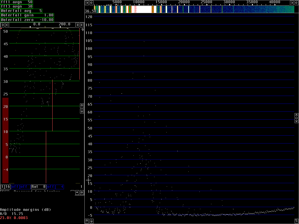
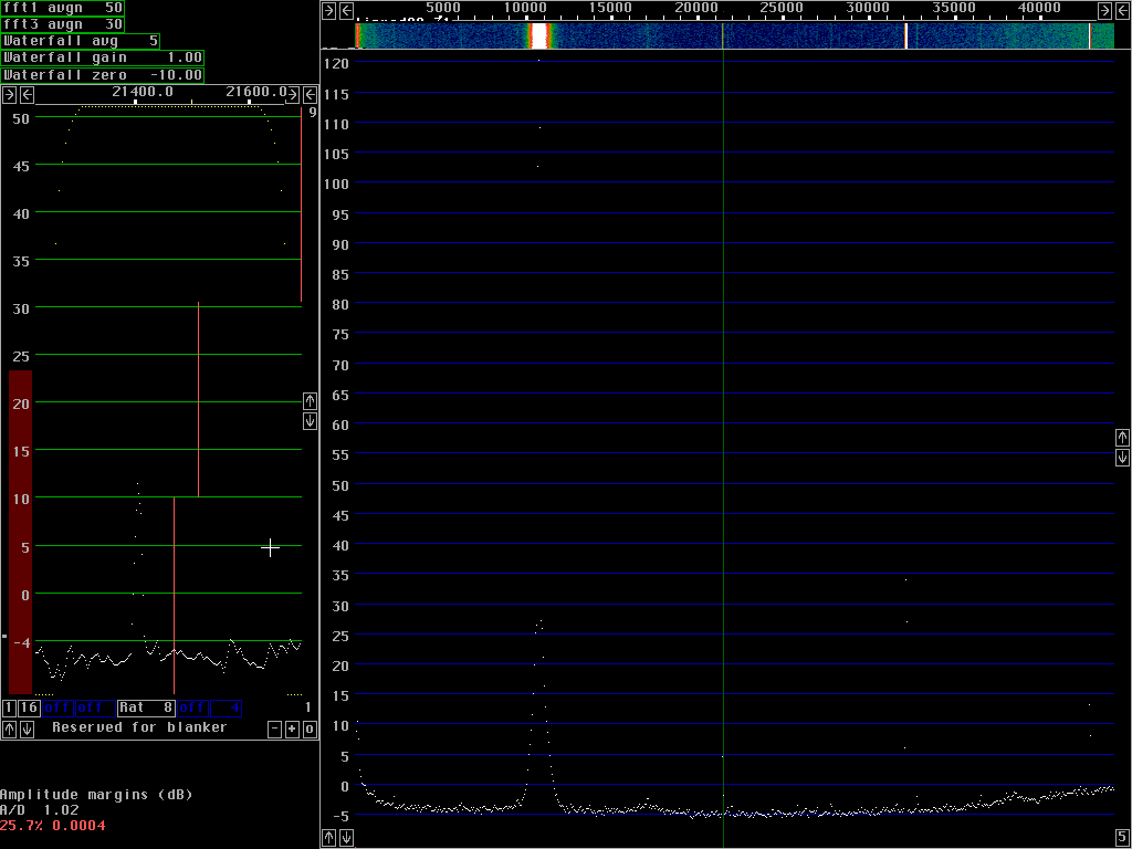
Fundamental       2nd harmonic     3rd harmonic      4th harmonic
dB below           dB below         dB below          dB below
saturation        fundamental      fundamental       fundamental

    1                118                86               107
    3                109                92               119
    5                110                96               116
   10                109               108                -
   15                115               110                -
The overtones have a slightly oscillatory behaviour, the table
just gives an idea about typical values.
Unlike earlier tests on an unmodified board, this test shows
very low values for the second harmonic.
It is unclear if the old measurements did not have a clean
enough test signal or if the larger capacitors now present on
the board affect the linearity.
The harmonic distorsion is low enough to make it difficult to make a frequency mixer that will match the performance of the Delta44.
When the Delta44 is used as a baseband receiver, receiving I and Q in two analog channels, the signal will increase by 6dB while the noise will increase by 3dB only. In case the antenna is a crossed yagi system in 45 degrees the strong signals will be split between the two channels adding another 3dB to the system dynamic range.
For details of the Delta 44 modifications check this link.