SM 5 BSZ - The Linrad noise blanker. 16 bit integer vs floating point arithmetics.
(Oct 17 2004)

The noise blanker

A conventional noise blanker operates in a bandwidth of something like 15 kHz. It detects whenever the voltage of the signal within the passband is above normal and sets the signal to zero during such time intervals. The problem with a conventional blanker is that it zero is not the correct voltage to set during the interference pulse in case there is one or more strong signals within the passband. Setting the voltage corresponding to strong signals to zero is the same as keying the strong signals, something that is associated with keying clicks. By use of a narrower bandwidth one can reduce the risk of getting unwanted strong signals into the passband, but blanker performance is then degraded by the lengthening of the pulse and the correspondingly longer times during which the desired signal is lost.

One way of solving the problem when a noise blanker is implemented in a digital radio is to not set the signal to zero during the duration of a pulse, but to some value found by an interpolation from surrounding data points in the signal. Linrad uses this strategy in its most extreme form. The input signal is split into two parts. One, called strong signals that contains all those frequencies outside the desired passband on which the averaged power spectrum shows that narrowband signals are present, another, called weak signals that contains all other frequencies including the desired frequency band. The blanker operates on the weak signals which by definition does not contain any strong signal besides possibly the desired signal. When the two parts are subsequently summed, the final waveform is not zero during the duration of the pulse, it is a perfect interpolation over the time of the pulse using a fit in the FFT size to all the signals present among the strong signals.

The conventional blanker the dumb blanker in linrad operates as described above. In case the desired signal is a strong signal, the dumb blanker does not remove any pulses, it just replaces the pulses with keying clicks caused by keying the strong signal. That does not matter much because such keying clicks are in general much weaker than the desired signal itself. The conventional blanker will of course not remove the parts of the noise pulses that fall within the frequencies of the strong signals.

Besides the conventional blanker, Linrad has a pulse fitting and subtraction algorithm, the smart blanker which subtracts the most probable waveform associated with the interference pulse assuming that the pulse is wideband and therefore has a shape that is given by the pulse response of the hardware. The smart blanker does not produce any keying clicks, it is a linear process and it does not modulate any signal. Since the correct shape of the pulse is subtracted from the weak signal, the subtracted pulse will have energy within the frequency regions contained in the strong signals and this will cancel the pulse equally well at these frequencies provided that the gain is the same for the weak signals as for the strong signals. When using 16 bit arithmetics this is not possible, the strong signals are then subjected to a selective AGC that turns down the signal level for everything to fit within 16 bits. This has been necessary because the 16 bit MMX instructions are about three times faster than floating point or 32 bit integer arithmetics. In recent years, with the Pentium IV, it has become possible to use 32 bit floating point instructions without CPU overload and this makes Linrad easier to use because setup becomes much less critical. Setting the digital signal levels correctly is critical to preserve the good dynamic range of 24 bit A/D converters. With floating point arithmetics this problem disappears.

Screen dumps showing blanker operation

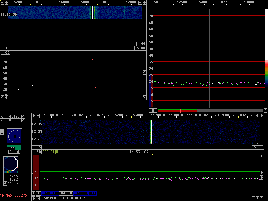
The images below show the Linrad screen on 14 MHz. The main spectrum is zoomed in to cover 12 kHz from 14.151 to 14.163 MHz. The WSE converters are used and the gain is set to 0 dB. The signal at 14.1531 MHz is -123 dBm, while the signal at 14.585 is at -77 dBm. Both signals are carriers from signal generators. All images have these two signals, some also have noise pulses with an amplitude of 0.5 V and a repetition rate of 73 Hz. The pulses have an essentially flat power spectrum from DC to 20 MHz. When filtered through the 93 kHz passband of the WSE converters, the pulses have a peak amplitude of -54 dBm, 23 dB above the signal at 14.163 MHz. In SSB bandwidth the peak power of the pulses is about 10 dB below the power of the signal at 14.163. All signals are fed to both inputs of the RXHFA unit through a hybrid and the power levels given are the power levels at each input.


Fig 1. Listening to the weak signal using 16 bit arithmetics. No pulses added. Note that the noise floor surrounding the strong signal is invisible because the waterfall is computed from the strong signals for all points that are red in the main spectrum.


Fig 2. Listening to the weak signal using floating point arithmetics. No pulses added. Note that the noise floor is visible close to the strong signal and that the spurs surrounding the strong signal have disappeared. These spurs can be removed by selecting a narrower bandwidth for the first FFT when 16 bit arithmetics is used.


Fig 3. Listening to the strong signal using 16 bit integer arithmetics. No pulses added. It is obvious that the frequency range surrounding the strong signal is attenuated (by about 12 dB). This is necessary to make the signal fit into 16 bits. It is necessary to attenuate all frequencies that fall within the desired bandwidth (with some margin) by the same amount, otherwise the signal would become distorted.


Fig 4. Listening to the strong signal using floating point arithmetics. No pulses added. Both strong and weak signals are treated with the same gain. Note that the weak noise sidebands that surround the strong signal in fig. 3 are not present here. They are generated by quantization noise due to the rounding errors caused by truncation to 16 bits.


Fig 5. Listening to the weak signal using 16 bit arithmetics. Pulses are added and the smart blanker is running. Note that the smart blanker does not work in the region close to the strong signal where the subtracted signal is wrong in amplitude by about 12 dB. It does not affect the desired passband but it could make the selective limiter treat the noise as if the strong signal was covering a wider frequency range. To avoid such problems, the red bar at the left side of the high resolution graph must not be set too low.


Fig 6. Listening to the weak signal using floating point arithmetics. Pulses are added and the smart blanker is running. Note that the smart blanker works properly on all frequencies.


Fig 7. Listening to the strong signal using 16 bit arithmetics. Pulses are added and the smart blanker is running. The frequency range over which the gain is reduced is much wider here as compared to fig. 5 because the entire frequency range wanted for the baseband has to have the same gain. It may look as if this is a hopeless situation, but the strong signal is still high above the noise floor so intelligibility would not be lost if it were a CW or SSB signal.


Fig 8. Listening to the strong signal using floating point arithmetics. Pulses are added and the smart blanker is running. Note that the smart blanker works properly on all frequencies. It does not matter that a wider frequency range is routed among the strong signals. The shape of the interference pulses is deduced from a very much wider bandwidth and it provides good cancellation.


Fig 9. Listening to the weak signal using 16 bit arithmetics. Pulses are added but no blanker is running. The interference level is (of course) about 12 dB lower in the immediate surroundings of the strong signal.


Fig 10. Listening to the weak signal using floating point arithmetics. Pulses are added but no blanker is running. The flat noise floor close to the strong signal does not improve the reception of the weak signal at all.


Fig 11. Listening to the strong signal using 16 bit arithmetics. Pulses are added but no blanker is running. The interference level is (of course) about 12 dB lower in the immediate surroundings of the strong signal. Note that the noise floor is flat close to the strong signal. The interference from the pulse generator is much stronger than the noise sidebands caused by quantisation noise.


Fig 12. Listening to the weak signal using floating point arithmetics. Pulses are added but no blanker is running. There is nothing particular about this image.


Fig 13. Listening to the weak signal using 16 bit arithmetics. Pulses are added and the dumb blanker is running. Note that this blanker is a little better in that the noise floor close to the weak signal does not change at all when the pulse generator is switched on. On the other hand the strong signal is surrounded by "keying-click" sidebands because some of the signal energy belonging to the strong signal is routed among the weak signals. The pulse interference within the frequency range routed among the strong signals is of course not attenuated at all.


Fig 14. Listening to the weak signal using floating point arithmetics. Pulses are added and the dumb blanker is running. The fact that the pulse noise close to the strong signal is removed is unexpected. I have no explanation.


Fig 15. Listening to the strong signal using 16 bit arithmetics. Pulses are added and the dumb blanker is running. The "keying sidebands" are strong, the dumb blanker does not work with a strong signal keyed off during the duration of each pulse.


Fig 16. Listening to the strong signal using floating point arithmetics. Pulses are added and the dumb blanker is running. Floating point arithmetics does not improve.


Fig 17. Listening to the weak signal using floating point arithmetics. Pulses are added and the dumb blanker is running. Here the first fft uses a narrower bandwidth with steeper skirts, a sine to power 3 window. Compared to figure 14, the keying sidebands have disappeared because all the energy of the strong signal is routed among the strong signals because of the steeper filter. In real usage better filters will not give the improvement from figure 14 to this figure because the spectrum of modulated signals typically have tails that will cause some energy within the weak signals. In real usage with many modulated signals it is advantageous to use the smart blanker to remove most of the pulse energy by subtraction because subtracting pulses does not generate keying clicks. The dumb blanker can be used to remove the small (short) pulses that remain due to the errors caused by having a large portion of the spectrum routed through the strong signal path. The dumb blanker does not work always. The keying clicks caused by it can degrade S/N. A blanker operating in the baseband could be very useful in such cases. Space is reserved in the baseband window for controlling it. I have not made any attempts to implement it because of lack of suitable test signals. A baseband blanker would probably improve reception on low bands where QRN from distant thunderstorms can be a problem.