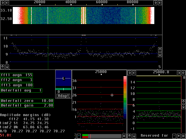
Different routines for the second fftThere are different routines for the second fft. Firstly because I always write the algorithm in C to start with, translating it into assembly of one kind or another afterwords so I can compare the assembly routine results to the C routine which is easier to make correct.Having C routines in the code, there is a good reason to leave them in place because older computers do not support MMX or SIMD. In case the C routines, vers 0 or 1 for second fft is selected, all processing uses floating point and there is no reason to worry about the "Second forward FFT att. N" parameter. It does not affect the floating point routines at all. The MMX version, vers 2 for second fft, is very much faster than the floating point routine. In case one wants to look for really weak and really stable signals over a wide frequency band, for example in 144MHz EME it is meaningful to run very large transforms and that is not possible without the MMX routine, at least not using the PentiumIII at 650MHz. Using too much attenuation in the second fft causes rounding errors that have a typical effect as shown in fig.1. All the screen dumps below were produced with second fft size=131072 and sin squared windows.
|

|
The attenuation N is 10 for fig.1 corresponding to 60dB.
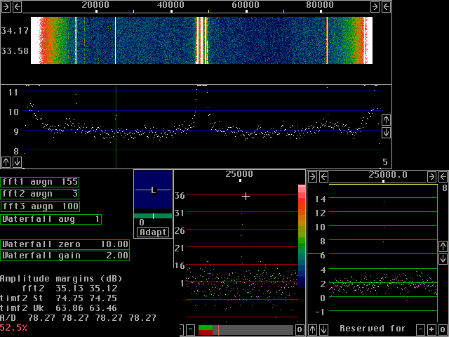
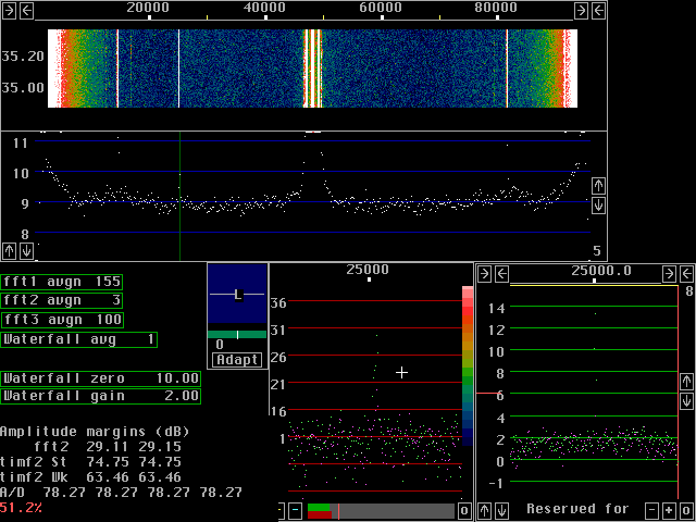
Below are several figures showing screen dumps with attenuation
reduced in 6dB steps, fig. 2 to 4.
The S/N ratio for the weak signal is degraded in fig.1 but already
6dB less attenuation gives nearly full S/N.
The selective limiter has information from fft1 and that is used to ensure no very strong signals will show up in fft2. Therefore it is possible to use rather small values for the attenuation N without saturation. The way to set the "Second forward FFT att. N" parameter is to run the receiver with the amplitude margin display enabled for a while as the last step after having decided what value to use for other parameters that affect the fft2 signal level Select a value that gives some margin to saturation in worst cases.
|


