The diagonal waveguide feed has been around for a long time but little has been done with it amongst the amateur community.(1) It is known that the feed will support linear or circular polarization.(2) However, what information was available did not indicate its use for anything but .35 f/D dishes in linear polarization.
Whereas, rectangular or circular feeds have undesirable characteristics which produce asymmetric E and H-fields, the diagonal feed is one of just a few which has almost symmetric E and H-fields and low sidelobes.
The circular feed has high side and rear lobes due to high edge currents around the mouth of the guide. It, however, can be satisfactorily utilized by using choke rings around the mouth of the feed to reduce the edge currents and equalize the difference in the E and H-plane radiation pattern. Unfortunately this produces some dish blockage when the feed is used with small TVRO dishes.
There is one better method to make use of a circular feed, that is to convert the operating mode internally in the feed from its normal TE11 to TM11. The TM11 mode produces very low edge currents. This is precisely what is done in the W21MU dual-mode feed in its Drift Section.(3)
The diagonal feed requires no choke rings or mode conversion to modify its radiation pattern which results in increased efficiency.
There is considerable versatility to this feed. First, it lends itself to crossed-dipole excitation instead of E-field probes, resulting in much better VSWR control. It can be used with an external hybrid for clean circular polarization that is within +/- O.5 dB if a quality hybrid is used. When used this way the typical cross-polarization is -35 dB and typical VSWR is 1:03. It can be used with strictly linear polarization using one dipole or it can be used with internal polarizer stubs with a circularity of +/- 0.5dB. In that configuration the isolation (cross polarization) is -26dB with the use of a nulling post or -19 dB without. Return loss is typically 28dB for both ports.

One fact that has not been mentioned in various references is that the diagonal feed can be used with almost any conventional f/D dish simply by constructing the proper size, within limitations. These limitations are: the feed size must be between the fc, lower cutoff frequency and ft, the transition frequency to the next higher mode which is TMOI. The normal operating mode for diagonal waveguide is TE11.
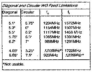
The following table gives the cutoff and transition frequencies for various size diagonal and circular feeds.

In looking at the table above you will note that a 5.1" diagonal feed and a 5.75" circular
feed have the same fc and ft. This is because both have the same square inch internal area
propagating the E and H-fields.
Note, cutoff frequency, fc is derived from: circular guide diameter * 1.706 = wavelength in
inches.
Transition frequency, ft, is derived from: 1.3065 * diameter = wavelength in inches.
It is best to avoid operating any waveguide near the Fc Lower Cutoff Frequency, the
attenuation at that point is rather quick and dramatic.
Operation near or at the Ft, Transition Frequency is not quite as well defined.
Once the point is crossed the dominant mode can switch to TM01, and if it does
you immediately are cross polarized from what you want.
A "rule-of-thumb" for diagonal and circular feeds is that the smaller the feed dimensions,
the wider the beamwidth. But, as the feed gets smaller the required length gets longer.
The length of the feed is based upon guide-wavelength which is determined by fc md the
free-space wavelength.
The following table shows the guide-wavelength
Guide-wavelength is an important factor and necessary In calculating a workable diagonal
waveguide feed or 'any rear-excited waveguide feed for that matter. Regarding the 1/8wg,
measurement in mm, that departure from our normal measurement system is necessary for
better accuracy since this value is used in spacing polarizer stubs.
Understanding guide-wavelength is a bit akin to science fiction. Wave travel inside a
waveguide is in such a manner that the apparent velocity of the wave seems to exceed the
speed of light. If we actually measured the nulls between half-waves with a slotted
waveguide section we would find that they are longer than a free-space half-wavelength,
hence the term 'guide-wavelength' which is longer than a free-space wavelength.
It Is because of this characteristic that wo have to know just what the guide-wavelength
is so we can allow a clean wave transition to free space.
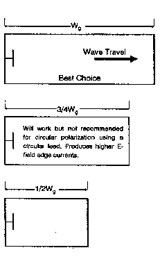
There are several ways of building acceptable diagonal feeds, some are shown below.
The following lengths are recommended for either linear polarization or circular polariza-
tion using a hybrid.
The following recommended length applies only to a diagonal feed with internal polarizer
stubs.
The following tables give the values for bandwidth based on diagonal and circular feed size.
The Low Noise value is based on an edge illumination that is lOdB down with no consideration
for space taper loss. The Max Gain value is based on an edge illumination value that is
lOdB down Including space taper loss.
Although it appears that there is a limit to the size of the diagonal feed that can be used
and thereby a limit to the beamwidths that can be obtained, this is only true for the
widest of beamwidths. But, the widest of beamwidths will illuminate any of the deep TVRO
dishes so there is no limitation here.
Narrower beamwidths can be obtained by simply flaring out all four sides of the mouth of
the feed at a preferable angle of 5 to 7 degrees maximum.
P>
With some experimentation the diagonal feed can be made to produce very narrow beamwidths.
Since most dishes are in the .5 f/D category the 6.2" diagonal feed should suffice but if
it doesn't, the following example can give you an idea of what you can do.
Illustrated is a 6.2" diagonal feed with a beamwidth of 127 degrees that has been flared
out to 7 degrees to produce a beamwidth of 113 degrees. This feed would then be suitable
for a low-noise f/D of .465 or max gain f/D of .52.
The diagonal waveguide feed can be made from 26 guage galvanized sheet metal or .040
aluminum. Either is plenty strong and lightweight and both work equally as well. Using
copper or brass is not warranted. A crimp fold is not recommended for joining the fold
joint together, it is recommended that spot welding be used, with the welds spaced no
greater than 1" apart.
A 1/16" thick copper or aluminum strip, 10 wide, should be installed where the polarizer
screws are located to reinforce that area and insure that the screws remain straight.
In the case of a sheet metal guide, solder the copper to the guide. If you chose aluminum
for the guide material, have the strip spot welded or heliarced.
There are two options for feeding the dipoles. One is to use semi-rigid 141 for feeding
both dipoles if the RF power at the feed does not exceed 300W.
If more than 30OW is available, convert the transmit port to air-line feed.
The feeds circularity is dependent upon how accurate the feed is made. Make sure the feed
is truly square. The placement of the polarizer screws will also affect the circularity.
Each polarizer screw must be equally spaced from the other. Also the rear plate must be
made of a rigid material so it does not 'oil-can'.
This is easily done by placing a horizontally polarized non-resonant dipole on a tripod
located no closer than 45 inches to the mouth of the feed. The feed should be placed on a
convenient table so that it is at least 30 inches off the ground. Orient one of the feed
dipoles in the same plane as the non-resonant test dipole. Using a low level signal fed
to that feed dipole, measure the output level then feed the low level signal to the other
port, after orienting that dipole to the test dipole. The output levels should be identical.
If they are not, readjust the length of the dipoles for maximum signal and minimum VSWR.
The phase point of the diagonal waveguide feed is located between I" and 1-1/2" inside the
mouth of the feed.
      (5.162)^2 = 26.Ol sq.in.;

      (5.75)^2  *  .7854 = 25.97 sq.in.
This can be verified easily by measuring fc. Both feeds will have the same measured fc.
This is also true for the remainder of the feeds.


Construction
Initial Adjustment
Verify that the total length of both dipoles are equal. Just a small deviation can result
in up to a ldB loss in one circularity versus the other. It is recommended that a non-resonant
dipole be used with a powermeter such an the HP 432 to verity that both ports produce
identical output levels.
Internal Polarizer Adjustment
     1 - Situate the helix on a tripod, at least 6' from the mouth of the feed and centered on
         the feed.

     2 - Connect a 1296MHz signal source to the  left-hand port RHCP (as viewed from the rear of
         the feed).

     3 - Set all polarizer screws so only 1-1/4% protrudes into the feed.

     4 - Connect a power meter (HP-432, etc.) to the helix.

     5 - Connect a dummy load (5 or 1OW rated for 1296MHz) to the right-hand port. Adjust the
         signal source for approximately -5dBm on the power meter.

     6 - This step requires adjusting the pblarizer screws in specific sequence. If you have any
         difficulty, most of the time it Is caused by reflections from your body. Try
         repositioning yourself.

     A - Adjust screw pair #5 inward, in equal amounts, for a null. Do not go past this point
         as there is a second and incorrect null.

     B - Adjust screw pairs 4, 3, 2 and I for nulls. You will notice that pair 2 has the least
         distinct null.

     C - Go back and adjust screw pair 5, then 4, 3, 2 and 1 to refine the nulls. You should
         have realized a reduction in signal levell by a t least 25dB from the
         original level noted before you started adjustment.

     D - Visually check the screws, they should all be the same length. If not, go back and
         readjust them until they are, making sure that each screw pair has a distinct null.

     E - Install the nulling screw.  Feed the test signal into one port (at a reduced level)
         measure the cross coupling at the other port. Adjust the nulling screw for minimum
         coupling.

     F - Install the test dipole in place of the helix antenna. Feed the test signal into one
         port, dummy the other. Check the circularity by rotating the feed on the table. I prefer to use a Black & Decker
         Workmate table since the center of it can be opened up allowing the feed to be cradled
         in it while rotating.
If you have to go back and redo your polarizer screws, always re-check the nulling scresw
adjustment. Pair 5 will change the nulling screw setting.


     (1)  Love, Electromagnetic Horn Antennas, New York IEEE Press, 1976
     (2)  Dick Turrin, W21MU, Parabolic Reflector Antennas and Feeds, P 9-29, ARRL UHF
          Experimenters Manual, 1991
     ()   Turrin, P 9-31
W6/PA0ZN